Saulo35
Member
Hi,
Short version: the OK LED of a 1756-CNB/E in a redundant system flashes green.
The alphanumeric display cycles OK / %C30 / KpIv / nC00 / A#02 (the number after the %C varies - it's the CPU loading - it's OK)
I have a redundant system as follows:
Chassis 1
1756-A4
0 - 1756-CN2/B/20.020.602800 - Node 5
1 - 1756-EN2T/C/5.008.700300 - IP Address 192.168.1.2
2 - 1756-L61/B/20.054.110
3 - 1756-RM/B/3.003.7
Chassis 2 (Identical to Chassis 1)
1756-A4
0 - 1756-CN2/B/20.020.602800 - Node 5
1 - 1756-EN2T/C/5.008.700300 - IP Address 192.168.1.2
2 - 1756-L61/B/20.054.110
3 - 1756-RM/B/3.003.7
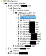
I/O Chassis
1756-A13
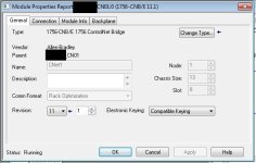
0 - 1756-CNB/E/11.004 - Node 1
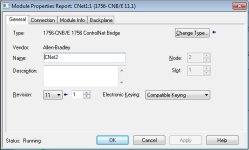
1 - 1756-CNB/E/11.004 - Node 2 (THIS IS THE ONE FLASHING)
2 - 1756-IF16/A/1.005
3 - 1756-IF16/A/1.005
4 - 1756-OF8/A/1.005
5 - 1756-OF8/A/1.005
6 - 1756-OF8/A/1.005
7 - 1756-OW16I/A/3.002
8 - 1756-OW16I/A/3.002
9 - 1756-OW16I/A/3.002
10 - 1756-IA16/A/3.003
11 - 1756-IA16/A/3.003
and a PanelView Plus 1500 at IP Address 192.168.1.1
Everything is working well, the redundant modules are doing their job (one is PRIM and the other is SYNC, the IP Addresses and ControlNet nodes flip when power to PRIM goes off, etc.).
The only consequence I see is that when I disconnect the ControlNet cable from the CNB in slot 0, all the I/O modules' OK LEDs turn red and the PRIM processor's IO LED starts blinking. Looks like the CNB in Slot 1 is not "takingg over". If I disconnect from the CNB in slot 1, nothing happens to the I/O modules.
I could not find an explanation for CNB's OK LED flashing green other than accompanied by error messages "CNFG ERR" and "NET ERR", which I don't have.
Any clues will be appreciated.
Thank you


