24 hour cycle timer

PaddyParki

Member
Join Date
Aug 2012
Location
London
Posts
4
Hi there,

I have an SLC503 that I'd like to control an external contact with. Basically I'd like to assert my local contact on the 503 every 12 hours and have the program cycle. Is this possible?

6am - on for 15 mins then off
6pm - on for 15 mins the off
Repeat

I'd like to be able to change the times so I will need 24hr instead of just switching every 12hrs.

Thanks for the help.
 
You can use the Status file (S:40-42 HH:MM:SS) to set your logic... The PLC clock is not extremely accurate, and your time will vary after while. You will need to set the clock every now and then.
 
Thanks for the reply.

Can I set the timer without any input to the PLC? If I need to I can set an input always high but I'm quite new at this.

Can you send a quick example?

Thanks again
 
Thanks for the reply.

Can I set the timer without any input to the PLC? If I need to I can set an input always high but I'm quite new at this.

Can you send a quick example?

Thanks again
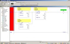
Just another way based on what Widelto said, almost the same, with a little more range to adjust values.
See Attached
 
Last edited:
Thanks for the reply.

Can I set the timer without any input to the PLC? If I need to I can set an input always high but I'm quite new at this.

Can you send a quick example?

Thanks again

I see you got some examples.

I'm not sure what you mean, "without any input" if you want the PLC to change, then you need to tell it to. You can change the time through an HMI, RS500, Or record the time, when an input turns on.
 
I am not very familiar with the AB family, but in Siemens there are a series of blocks you can use to sync with a time server.
 
I see you got some examples.

I'm not sure what you mean, "without any input" if you want the PLC to change, then you need to tell it to. You can change the time through an HMI, RS500, Or record the time, when an input turns on.

Thanks for the reply. I am new to this style of programming so forgive me if I get it wrong.

I was under the impression that a timer needed an input to start counting, but with the answers above I see I was mistaken. What I'm trying to do is control only an output, which in turn would make an external contact to the PLC.

I am unfamiliar with RSlogix so far - is there an RSS file that someone can post that has the functions shown above? I can't seem to find them.

Thanks
 
The functions "EQU" (equal) and "LIM" (limit) are found under the "Compare" tab in RSLogix 500.
 
Last edited:
Thanks very much, I understand now.

Now that I try to download though, no connection!

Does the 232 cable have to be null or direct?
 
Look under the status data file (S:2) it will be on the opening tab on the right.

You can use a timer, but a timer in the program, can vary up to the scan time of the program. A timer does not cause an immediate event, essentially at the point in the program where the Timer is accessed, it looks to make sure that the preset time has passed. If you have a 10ms scan time, and a preset of 1 second on your timer. In a scan your timer accumulation is at 0.99s then it will be return false. Now on the next scan your timer will set the dn bit, as it has been more than 1s, when in actuallity it is 1.09s. This compounds quickily, if you are trying to keep accurate time.

Now the clock frequency is not the most accurate on many PLC's, but it is independent of the scan time, not adding this error to the inaccuracy.

I hope this makes the reasoning clearer.

As to the other question, you do not need anything in front of a timer in AB to make it count. You will however need to reset the timer at some point, if you want it to count again. You can do this using the RES instruction or if a false enable into the TON. A common way to create a recycling timer is to use it's own dn bit in front of it. This will count to the preset value, set the /dn bit for 1 scan, and reset during the next scan.


T4:0
---|/|---------Ton T4:0 .01 100 0

 
Thanks for the reply. I am new to this style of programming

Visit ronbeaufort.com for excellent free step by step detailed lessons regarding ab PLCs.

PaddyParki said:
I was under the impression that a timer needed an input to start counting, but with the answers above I see I was mistaken. What I'm trying to do is control only an output, which in turn would make an external contact to the PLC.

In ladder logic, a bit box is a bit box. It can be a bit sized box or one bit of a 16 bit integer word. The PLC doesn't really care whether it came from a real world input "I" address, real world output "O" address, internal B3 file address, heck you can even examine one bit of a timer accumulator word in ladder logic and they all work the same.

I suggest you use the help file in RSLogix and learn the addressing syntax right away, and read up and watch ron's videos in order to get your head around the scan cycle.

Once you match the hardware manual for your particular model and i/o options to the addressing methods, it is pretty easy to work with.

PaddyParki said:
I am unfamiliar with RSlogix so far - is there an RSS file that someone can post that has the functions shown above? I can't seem to find them.

Thanks

The menu bar above the ladder editor window should have a tabbed palette of instructions. I think in the main options menu you can switch that menu off. I work mainly with the keyboard, you can type in the 3 digit mnemonics (XIC, TON, ADD, etc) and drag branches from menu or right click and get them...

Paul
 
The 5/03 has two configurable communication ports.
If you verify your cable is correct, then you can question whether this 5/03 has an existing configuration that you need to identify or reset.

For either port, you need a Driver configured in RSLinx to match.

The channel 1 port of the 5/03 is not ethernet! It is another multi-drop serial port called DH485, electrically like RS485, not compatible with patch cables and laptops! But the protocol is DH485.

Interestingly, the channel 0 DB9 serial port you are connecting to, can also be configured for this DH485 protocol, or ASCII mode which can lead to a great deal of flexibility and potential for issues communicating.

It is simple and easy to wipe out the settings restoring factory default to channel 0 if you have that option available. You just unplug the memory backup battery and short VBB to ground, and esure that no EEPROM in installed before doing so. This will wipe out any programs and comms settings for CH0. Then RSLinx will find it 99% of the time if your using it right and your cable is good.

The other 1% of the time is usually a bad port on the SLC or PC.

If using a USB to RS-232 converter, please tell us, special instructions may apply, and autoconfigure won't necessarily work.
 

Similar Topics

Greetings everyone, I am writing an application for a test cell. I am using an L24ER AB PLC and a 10 PVPlus 7. The end user would...
Replies
4
Views
1,951
Hello It is probably very simple question but what is the best way to go about altering two blowers every 24 hours? In my logic same blower will...
Replies
30
Views
7,781
Hello, I am trying to setup on plc so If I enter 60 jph (job per hour) it will send the vfd hertz based on what jph is entered by...
Replies
2
Views
160
Hi team, I am setting up my first E200 overload unit. I came across parameter 205 StartsPerHour. The default setting is 2. I presume, the motor...
Replies
2
Views
498
Hello, I have inherited an old machine with a PLC unit that needs to be reset after a batter replacement. I don't know what I'm doing! Here's...
Replies
5
Views
1,034
Back
Top Bottom