AB 1756 Analog input IF8 iRTN & RTN

jc77

Member
Join Date
Jul 2021
Location
CA
Posts
2
Hello! I am trying to wrap my head around how to wire a 4-20mA sensor
to my AB 1756 ControlLogix IF8 Analog Input card. Could someone educate me on the purpose and use of the iRTN and RTN terminals on the card? (user manual image attached).

For my purpose, I have a 4-20mA ultrasonic flow meter that gives signal to a controller that connects to my analog input card via a single output wire (4-20mA). The controller has a wire for +24 and another for 0V which I plan on hooking up to +24 and 0V terminal boards connected to my power supply the PLC uses. I want to use channel 2 so I am planning on connecting the output wire to Input 4 (terminal 12) and having Input 5 (terminal 14) connect to 0V to complete the circuit. I am wondering if I am missing something by not utilizing the RTN/iRTN but I don't know because I am not sure what the purpose of those terminals is for.

From the user manual, it seems like those terminals are used primarily for differential mode, but I am not sure how to tell if that mode is what I need
to use for this ultrasonic sensor. Any answers you could give me or resources to understand this concept would be appreciated!
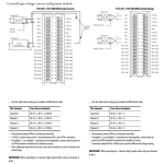
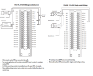
1756IF8diffvoltage_current.PNG 1756IF8single-endedcurrent_voltage.PNG
 
The entire 1756-IF8 is in either Differential or Single-Ended mode. This mode is set inside the Studio/RsLogix 5000 software. Changing this mode in software changes how the hardware is connected internally. In differential, two op-amps are used for one analog input, in Single-Ended one Op-Amp is used per analog input, and twice as many channels are available.

Once you have that figured out you need to figure out the sensors 4-20ma loop type: Feild powered or Loop Powered. active or passive. Once that is known, you can hook it up just like in the diagram. https://literature.rockwellautomation.com/idc/groups/literature/documents/um/1756-um009_-en-p.pdf
 
Last edited:
Hello! I am trying to wrap my head around how to wire a 4-20mA sensor
to my AB 1756 ControlLogix IF8 Analog Input card. Could someone educate me on the purpose and use of the iRTN and RTN terminals on the card? (user manual image attached).

For my purpose, I have a 4-20mA ultrasonic flow meter that gives signal to a controller that connects to my analog input card via a single output wire (4-20mA). The controller has a wire for +24 and another for 0V which I plan on hooking up to +24 and 0V terminal boards connected to my power supply the PLC uses. I want to use channel 2 so I am planning on connecting the output wire to Input 4 (terminal 12) and having Input 5 (terminal 14) connect to 0V to complete the circuit. I am wondering if I am missing something by not utilizing the RTN/iRTN but I don't know because I am not sure what the purpose of those terminals is for.

From the user manual, it seems like those terminals are used primarily for differential mode, but I am not sure how to tell if that mode is what I need
to use for this ultrasonic sensor. Any answers you could give me or resources to understand this concept would be appreciated!

All PLC analog inputs are really voltage inputs, even when you're using 4-20mA transmitters. In order to convert the transmitter's current signal into a voltage signal, you insert a 250Ω resistor across the analog input positive and negative terminals and measure voltage drop across the resistor. 4mA = 1V and 20mA = 5V.

The iRTN terminals internally connect a 250Ω resistor between the analog input positive terminal (IN-0 for channel 0) and the iRTN terminal (iRTN-0 for channel 0). The iRTN terminal, when used, must also have a jumper installed to a RTN terminal in order to connect the negative side of the built-in resistor to DC common.

The RTN terminals are all common to one another and to PS negative.

So, you only use the iRTN terminals with a transmitter that outputs a current signal. For a voltage signal, you don't need the 250Ω resistor in the circuit, so you don't use the iRTN terminals for voltage signals. Just tie all of your negatives to RTN and connect the positives to the IN-x terminals.

In differential mode, every other IN-x terminal (beginning with IN-1), which is normally a positive terminal becomes the negative terminal. The inputs must be used in pairs in differential mode. IN-0 & IN-1, IN-2 & IN-3, IN-4 & IN-5...

You don't connect to the RTN terminals when using differential mode.
 
Last edited:

Similar Topics

Good Morning , I have a RTD , that I would like to wire into a 1756-IF8 Analog Input Card. Would you all a simple wiring diagram , of what...
Replies
4
Views
1,205
Good evening, just a dump question, I’ve configured channel no 13 with scalling as attached, then shown not linear reading, even when i simulate...
Replies
6
Views
1,707
Hello, I have a flow meter that has been in service for a few years now. I have recently noticed that my registration on the mag meter does not...
Replies
0
Views
1,123
Good Evening , I have a 1756-IF16 Analog Input card already installed in a working ControlLogix Rack. I need to add another Analog 4-20 ma...
Replies
1
Views
2,188
I am facing an issue module 1756-OF8 is showing the minor fault = recoverable in the module info.How can i reset it?
Replies
0
Views
1,767
Back
Top Bottom