AB PLC5 Analog Input Raw Min/Max Settings

hardaysknight

Lifetime Supporting Member
Join Date
Dec 2015
Location
Southeast USA
Posts
117
I've got a 4-20ma pressure transducer connected to an analog card on an AB PLC5. Under the setup for the card, I have to set a raw minimum and maximum input range. I'm confused about how to set this up.


The pressure transducer is an IFM PT5460. In the manual for it, it says that the input range is 0-600 bar, with a 1500 Pmax.


Should I set the min/max range to 0-600, or 0-1500 in the PLC5?
 
I could be wrong, but I would set it up for 0-600. I believe Pmax would be the maximum pressure that the instrument will physically handle. Again that could be completely wrong, but I believe 0-600 is the measurement range.

Where exactly are you setting this? I would expect "raw minimum and raw maximum input range" to be the range of raw counts (i.e. 0-4095 is 4-20mA). Are these going to be set using BTW/BTRs?
 
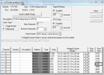
Oceansoul is right. Here's a picture of an analog input setup on a PLC5.


To calibrate the value the MAX is manipulated, then to get the reading you want you need to scale the calibrated input to your desired range.


EDIT: These settings are set through RSLogix5 and written directly to the analog cards once, not through the BTW. Then the PLC program does the BTR


EDIT #2: Rockwell says the PLC5 analog IO needs calibrated annually, and I have found this to be needed while a SLC analog IO can run it's life without needing recalibrated after the initial setup.

Plate2 Anlg Input Rack 3 Group 7 Settings.JPG
 
Last edited:
Oceansoul is right. Here's a picture of an analog input setup on a PLC5.


To calibrate the value the MAX is manipulated, then to get the reading you want you need to scale the calibrated input to your desired range.


EDIT: These settings are set through RSLogix5 and written directly to the analog cards once, not through the BTW. Then the PLC program does the BTR


EDIT #2: Rockwell says the PLC5 analog IO needs calibrated annually, and I have found this to be needed while a SLC analog IO can run it's life without needing recalibrated after the initial setup.

Great info, thanks. I only have limited experience with PLC-5s, so I haven't seen that analog input module setup screen before. I've only seen it done by using the BTW to send the config, also familiar with this from working on SLC programs as well. And I also suspected that OP was referring to the min and max raw counts shown in your window, which would then need to be scaled using a scale (SCL - does PLC5 have an SCP?) instruction to correlate 0-4095 (or whatever the min and max values are) to engineering units, likely 0-600 in his case.
 
I understand everyone is saying that the range needs to be set for 0 - 4095 for 4-20ma, but I'm not understanding exactly why.

Shouldn't the card be able to automatically scale the input based on what I enter there? I currently have the range set to 0-600 and it appears to be working correctly.


EDIT: Setting the raw input range on a known value from a transducer to 0-600 gives me the correct value of 142 bar. Setting the raw input range to 0-4095 then scaling the input by dividing the input by 6.825 (4095/6.825 gives me the max range of 600) also gives me the correct value of 142 bar. I'm not sure why I would want to go that route.
 
Last edited:
I understand everyone is saying that the range needs to be set for 0 - 4095 for 4-20ma, but I'm not understanding exactly why.

Shouldn't the card be able to automatically scale the input based on what I enter there? I currently have the range set to 0-600 and it appears to be working correctly.

0-4095 is the data range for a 12-bit resolution A-D converter; 2^12 = 4096, or 0-4095. So essentially it's converting 4mA to 0, 8mA as 1024, 12mA as 2048, 16mA as 3072 and 20mA as 4096 (4mA may be 819 and 0mA is 0, often forget which modules will actually measure below 4mA). So the raw min/raw max values are supposed to be this upper and lower range of data counts that the card can expect to see. You would then typically use a scale (SCL) instruction to basically tell the PLC that 0 in raw counts is equal to 0 bar, and 4096 in raw counts is equal to 600 bar.

As for why it seems to be working with raw min and max set 0-600, I have no real idea. Could be luck or coincidence, or I could be completely wrong :ROFLMAO:


Thanks for the response. According to chapter 4 page 6 of this manual:
https://literature.rockwellautomation.com/idc/groups/literature/documents/um/1771-um663_-en-p.pdf


It seems that it CAN scale like I'm doing here.


EDIT: posted wrong manual link
 
Last edited:
It seems that it CAN scale like I'm doing here.


You CAN do a heck of a lot of things in a PLC, but SHOULD overrides a lot of that.


If anyone in the future gets in your program they are going to track you down and ask you What The H3!! Were You Doing?


When you look back at your programs in 20 years with much more experience even you will cuss yourself out, and look at things and wonder why that program hasn't killed or maimed someone.


Also, if you set the MAX to 600 you are cutting the resolution of the reading from 4095/20 to 600/20 (almost 7 times less if writing to an integer) and if you want to do something different with the raw data in the future the higher resolution might make a difference.
 
When you scale the card to 0-600, your 16mA range is divided in to 600 "slices". Your resolution will be 1.0. When you scale to 0-4095, you are dividing the range into 4095 slices. So you resolution will be 600/4095, equals 0.146

With the 0-600 scaling, you will never detect less than 1 bar changes in pressure. With the 0-4095 scaling, you can detect changes of .146. Your process will dictate which is better for your situation.

Back in the good ole days. We would often scale a 0-100 input as 0-1000 and then add the decimal via the Displays. The old non-enhanced PLC-5's did not have the compute instruction, so scaling was more difficult.
 
You CAN do a heck of a lot of things in a PLC, but SHOULD overrides a lot of that.


If anyone in the future gets in your program they are going to track you down and ask you What The H3!! Were You Doing?


When you look back at your programs in 20 years with much more experience even you will cuss yourself out, and look at things and wonder why that program hasn't killed or maimed someone.


Also, if you set the MAX to 600 you are cutting the resolution of the reading from 4095/20 to 600/20 (almost 7 times less if writing to an integer) and if you want to do something different with the raw data in the future the higher resolution might make a difference.


Yeah, I understand that. However, I did not originally program this PLC. Whoever programmed it originally scaled the analog inputs this way. The only reason I am even touching it is because it was originally set for 0-10v, and we did not have any replacement sensors of that type, so I had to reconfigure everything for 4-20ma.


As far as losing resolution, this doesn't have to be an exact calculation. I'm not bringing it out to multiple decimal places or anything.


I'm scaling it in the card settings in order to keep it standard with how literally every other analog input in our plant was set up. To change it now only introduces confusion.
 
, so I had to reconfigure everything for 4-20ma.


If the MIN is 0 then the PLC will give a 0 reading for 0.00mA, with a 4-20mA device it will always get 4mA so a 0 device transmit would show as (30 counts per mA) 120 and never lower. (Except device failure or wire break)


For the range you want of 0-600 you would have to set the MAX at 600, but the MIN Negative to something like -141 so that a 4mA input would display 0. You might need to tweak that MIN value to get exactly 0.


EDIT: This is also a good reason to range the input 0-4095 and scale your value in the PLC
 
Last edited:

Similar Topics

Hi Guys, Im Re-writting a program from 6200 to RS Logix5k. Ive completed all the digital i/o's and logic that goes along with it. Now I just...
Replies
3
Views
4,360
Has anyone ever calibrated an analog Input module for a PLC5? Was it worth the effort? I have a REV C 8 channel input module in a new project...
Replies
16
Views
6,987
we have a problem with redundant processor PLC5 where there is analog input value be stable with the primary processor. and at fault when working...
Replies
3
Views
3,102
I'm trying to open the BTR/W Setup Screen for pre-existing BTR/W's in Logix5 and getting the warning "no module exist in I/O configuration". I...
Replies
3
Views
6,150
I have an old PLC5 program with block transfers for many A/I cards. The "setup screens" won't come up because the modules were never added to the...
Replies
7
Views
5,082
Back
Top Bottom