ADD Function in TIA PORTAL

It sounds like you already have a sensor, so why do it the hard way, as I said before although it may seem to work short term, over a long period just adding/subracting a constant based on a pump running it will go out of sync, a pump does not deliver a constant flow on startup & shut down & other possible interferences i.e. friction, pressure etc. the only other way is to have full & empty probes, that way when full or empty could use the probes to re-calibrate the levels.
No i don't have the sensor, i'm just learning PLC to aquire enoght knowledge to make a living out of it, the sensor i have mentioned is the kind used in factories as i know, i'm looking for ways to simulate inputes so i can learn more.
In reality there is lot of interfrences must be considered
 
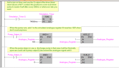
When I am simulating a tank level, for example in a tank that is supplying a process but has a feed pump to implement control of it's level, I have the code
  • subtract 1 "level unit" (e.g. 512.0-1]) every scan cycle to emulate the process, and
  • add 2 level units every scan cycle when the pum
  • is running.
So if the pump is not running, the level decreases, but if the pump is running then the level increases. Obviously I can play with the ratio between those [level units per scan cycle] rates.

If the "process" could also be running or not, then the subtract is also conditional.

If the control is via feedback, for example via a PID (though D is turned off, and sometimes I as well), then the add increment (per scan cycle rate) is scaled from the PID output CV.
This kind of making sense, but i'm still not in PID level yet even though it could be easier, i'm trying to figure out how to handel programming and HMI for different scenarios
For now i made it work using the BAR element in HMI for the analog input (0-27648) and using norm_x scale_x to make it (0-100%) working in good time to visual it normaly .
Now i'll be editing the program and combine the other process

If you are simulating your process in the PLC, then you will learn twice as fast: one path figuring out how to control the process; one path figuring out how to model the process.

Feel free to ask questions here; there is a lot of experience available.
 
Yes Brian is right it is common practice when simulating to disable the analogue conversion & create some temporary logic to simulate the increase or decrease of an analogue value, I do this all the time when simulating. it means by providing a "count" up or down you can actually simulate in a slow or fast mode handy then in the real process may take several minutes or even hours to cycle a tank from empty to full or vice versa.
 
If you are simulating your process in the PLC, then you will learn twice as fast: one path figuring out how to control the process; one path figuring out how to model the process.

Feel free to ask questions here; there is a lot of experience available.
I don't have any hardware yet i'm just using TIA PORTAL, WINCC and PLC SIM
I'll for sur ask thank you
 
Yes Brian is right it is common practice when simulating to disable the analogue conversion & create some temporary logic to simulate the increase or decrease of an analogue value, I do this all the time when simulating. it means by providing a "count" up or down you can actually simulate in a slow or fast mode handy then in the real process may take several minutes or even hours to cycle a tank from empty to full or vice versa.
That is exactly what i was trying to do, even thought of using PWM for the count
While pump is on it generate PWM pulse to increment the count, unfortenetly couldnt make it hapen.
 
It is simple, I am making some assumptions here you have an analogue level configured, disable the analogue signal i.e. if in a seperate program block do not call it, create a simulation block & add the simulation code or if you only have one continuous program replace the analogue value register with a spare so the real analogue does not write to it then use that register in the simulation block, if you only have the one pump (would assume there is a feed pump & a discharge pump so either way use the single pump or both pumps to add & subtract the level ion the register, once tested, delete the simulation code & put the correct register back in the analogue process.
 

Attachments

  • analogue level simulation.png
    analogue level simulation.png
    102 KB · Views: 0
Actually, this brings up an interesting point, the PLC user programs do not read input channels or write output channels: PLC user programs may direct the PLC what values to read from and write to the I/O channels, but the user program itself only reads from and writes to internal, non-I/O hardware, memory.
 
Yes yes & no, If you use imidiate functions (on many PLC's they read directly & update the image or individual I/O rather than say at end or begining of scan).
Also as the image is updated possibly at other times rather than in the scan it may overwrite any moves programmed in the scan what I normally do is map the Inputs in a seperate program block that can be false on the call, & enable a call to the simulation block, I do this rather than use some simulators own programming interface to simulate as I find it faster & easier to do, most simulators don't have very good scripting language if at all.
 
So, some of the big boys, such as Siemens PCS7, and Delta V, DCS systems. Sell simulation suites. They have many built in simulation "blocks". So all valves open close with feedback, there are integration blocks for filling or emptying vessels. Using one of these products, you can over time, model your entire process.

One of my employers did this, and used the model system to train/certify operators at an OSHA PSM plant (they must be re-certified annually). The trainer had the ability to accelerate the batch process, and introduce upsets.
Took a lot of time and money, but was well worth it. Process engineers could try new methods without causing a "Major Bad Event".
 
Yes yes & no, If you use imidiate functions (on many PLC's they read directly & update the image or individual I/O rather than say at end or begining of scan).
Also as the image is updated possibly at other times rather than in the scan it may overwrite any moves programmed in the scan what I normally do is map the Inputs in a seperate program block that can be false on the call, & enable a call to the simulation block, I do this rather than use some simulators own programming interface to simulate as I find it faster & easier to do, most simulators don't have very good scripting language if at all.

Of course there are exceptions: I knew about immediate functions, which the user program can call, and about asynchronous I/O (which is not a counterexample* anyway). But as you say, even with immediate functions, the PLC user program still only writes to or reads from the I/O memory buffer ("image"), and the immediate instruction only triggers an immediate copy from or to, respectively the memory buffer and the physical I/O channel, i.e. the PLC user program may be able to influence when the data transfer between memory and the physical I/O occurs, but the user program never directly interacts with the the I/O channels i.e. without the I/O memory buffer (image) as an intermediary.

* Asynchronous I/O still writes the physical I/O data to memory buffers, and the user program only looks at those memory buffers.

But in general, PLC user programs write to memory, which is why I can do something like in the image below (at least in RSLogix 500), where the rest of the user program can run, without changes, in
  • EITHER normal operating mode,
    • reading the physical input values that have been buffered to I:0.0 memory by the I/O subsystem at the start of every scan cycle, and
    • writing output values to the O:0.0 memory buffer that are copied to the physical outputs
  • OR simulation mode
    • reading the simulated inputs values that have been buffered to I:0.0 by the simulation (LAD15) at the start of every scan cycle, and
    • writing output values to the O:0.0 memory buffer that is passed to the simulation on the next scan cycle.

Untitled.png
 
So, some of the big boys, such as Siemens PCS7, and Delta V, DCS systems. Sell simulation suites. They have many built in simulation "blocks". So all valves open close with feedback, there are integration blocks for filling or emptying vessels. Using one of these products, you can over time, model your entire process.

One of my employers did this, and used the model system to train/certify operators at an OSHA PSM plant (they must be re-certified annually). The trainer had the ability to accelerate the batch process, and introduce upsets.
Took a lot of time and money, but was well worth it. Process engineers could try new methods without causing a "Major Bad Event".

I probably mentioned this before, but I used to work for a Large Oil Company a few decades ago, programming simulations that were "connected" to physical digital control hardware (Honeywell TDC 2000/3000) via a custom interface. The TDC saw "bits" but did not "know" (or care; why should it?) those data came from a simulation, instead of from a physical process with transducers via A/D converters, and the TDC controlled the simulated process as it would control the real process. The setup were used exactly as @Ken Moore describes above i.e. for operator training, but in an environment where mistakes could not cause physical mayhem. Eventually we coded the PIDs and other logic into the computer alongside the simulation, bought monitors and had custom keyboards and consoles made up, and replaced the (expensive) Honeywell hardware as well.

I remember after one acceptance test, the refinery representatives, who came to our offices to oberve the test, started working with the control console and simulation and discussing with each other about how they would operate the real thing, because their process unit was still being built and they had no other experience with it. I remember thinking "We did our best and it seems to work, but do they realize the simulation is not validated against the real thing?"
 
It is simple, I am making some assumptions here you have an analogue level configured, disable the analogue signal i.e. if in a separate program block do not call it, create a simulation block & add the simulation code or if you only have one continuous program replace the analogue value register with a spare so the real analogue does not write to it then use that register in the simulation block, if you only have the one pump (would assume there is a feed pump & a discharge pump so either way use the single pump or both pumps to add & subtract the level ion the register, once tested, delete the simulation code & put the correct register back in the analogue process.
YES I HAVE USED 2 PUMPS FOR CHARGING AND DISCHARGING AND SO FAR ALL GOOD WORKING FOR THAT PART.

in order to develop more i added 3 other tanks (flavors) to be mixed one at a time with product in first tank with switch button to select which tank I'll be using, the new 3 tanks use the same method as first one except that the filling process is not a pump but a i/o field input that number go in cycle of NORME/SCALE to display the volume in BAR element.
added some timers and counters as showing in the picture below.


1711730706204.png
 
Actually, this brings up an interesting point, the PLC user programs do not read input channels or write output channels: PLC user programs may direct the PLC what values to read from and write to the I/O channels, but the user program itself only reads from and writes to internal, non-I/O hardware, memory.
that was a problem i been facing from before (already posted a question about it here)
changing inputs values don't effect anything the opposite happens when i use Memory tag instead of input.
* still having this problem without solution ( i'm using memory tags a inputs)
 
Many years ago on the old Siemens S5 system an ex german engineer developed a simulator system it consisted of an interface card that fitted in the main rack & a card in a PC, you could do many simple things like valve & Motor I/O for example if the valve output came on you could put delays in to simulate the limit inputs there was no need for any real I/O as the interface card was the I/O, the pc program also had utility programs you wrote in turbo pascal to simulate any scenario you could think of this was better than any other simulator I have seen. this was called Prosis, brilliant for the 80's.
I do not understand why you are having problems, if you call the anlogue functions in a seperate program but do not call it in the main task then the value should not appear in the desired data tag, also, in that block map the real inputs to internal tags I usually give them names like for example the real Inputs are Valve1_Open_PX & the mapped internal tag as Valve1_Open_PX_M (the M desigates it as the mapped bits then only use the mapped bits in the program. then create a program block called simulation where for example you have simple logic like:
AND Valve1_Output Timer1, 3 s, = Valve1_Open_PX_M so it simulates the valve opening over a period of 3 seconds same with the analogues just map them or not call the analogue functions for simulation then just incremet/decrement the tag in the simulation block. see attached, here I have created 3 blocks, an I/O mapping block, main program & simulation block for simulation I only call the main program /7 simulation block the mapping block is not called I'm using the mapped bits in the program rather than real Inputs and as the mapping block is not called the simulation block mimicks the real inputs, when tested I remove the call to the simulation block & call the mapping block it's as simple as that
I kept it very very short just to show the way it operates
 

Attachments

  • Mapping.pdf
    92 KB · Views: 4

Similar Topics

I have a small system controlled by a Siemens S7-1200 PLC. I created a totalizer function block (TIA v17), where I'm counting total revolutions...
Replies
16
Views
3,138
I know this sounds really stupid, but I have a function block program I have written and have been debugging. I have an ADD block that will not...
Replies
10
Views
2,354
I am troubleshooting an outside vendor program where add on instructions are used as well as these user defined function blocks. I am trying to...
Replies
3
Views
1,599
Good afternoon, I'm using RS Logix 5000 on an AB 1769 L24ER-QBFC1B, and basically in my logic, whenever a prox switch is made, I want the...
Replies
5
Views
5,034
Hey everyone, I am new to using the LogicMaster 90-30 software for the GE Fanuc 90-30 PLC, and I needed some help in incrementing registers...
Replies
16
Views
5,928
Back
Top Bottom