Adding a second Wet well level

Cyanogen281

Member
Join Date
Oct 2013
Location
Houston
Posts
10
I am using a Siemens s7-300 PLC and need to add a second wet well level.

Basically the system will utilize the primary wet well level transmitter, but if for some reason the primary transmitter is malfunctioning the system will automatically switch to the auxiliary transmitter.

I am using a Maple system HMI for graphic interface.

How would I write the fail-over logic?

Any advice or examples would be greatly appreciated.
 
First you have to determine how you know the primary measurement is malfunctioning.

How do you know that?

What factor or signal indicates a failed primary reading? On ultrasonics, there's usually a relay that can be configured to trip on "Loss of Echo".

What does your primary technology offer as a fault mode?
 
If your transmitter produces a 4-20 mA signal, you can check to see if that signal is 0 mA. That means either the signal wire is disconnected, or the tranmitter has quit transmitting because of failure or loss of power. If it fails with a constant output, then you could use a timer to detect if the signal does not change in a long time period.
 
I am asking only about the PLC...

The transmitter has a 4-20 mA signal,

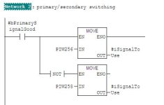
How would I go about designing the ladder logic inside the Siemens PLC?
 
I am using a scaling block to scale the output to around 35 feet.

Originally there was only one scaling block but I was thinking it would be possible to use identical scaling blocks and just have normally open contacts just ahead of them in the rung.

Can I used duplicate blocks with the same register names (since only one block is being read at a time) to accomplish this?
wND4MTEfv+67gAAAABJRU5ErkJggg==
 
Last edited:
I did something similar last year on an Omron CJ2M so the code won't help you but the principles might help some.
I did something very similar to what Lancie1 suggested with the addition of some logic that detects when one sensor is changing value but the other one isn't.
I read both sensors all the time and saved the converted values. The fault decision make was done by comparing these values. The fault logic drove a selection process to decide which sensor value to use.
 

Similar Topics

Hi,can you help me again? complete novice to PLCs. Using GT Designer/SoftGOT1000/Developer. Working on adding some Water Cooling parameters to an...
Replies
3
Views
1,211
Hello forum members, I have an existing L63 processor in a local rack communicating to a remote rack via controlnet. I would like to add a second...
Replies
1
Views
1,573
Hi, I need help adding a new interlock switch to an existing circuit. I have never done on the existing circuit. I did set it up on the...
Replies
6
Views
217
Hi all I’m looking at adding a RFID card reader to comfort panel pro , how do you set the rfid up can you connect to existing users and password...
Replies
0
Views
82
Hello all! So I have one project with a S7-1214 and a MTP1500 "Project1" and one project with another S7-1214 "Project2". Both of these PLC:s need...
Replies
6
Views
136
Back
Top Bottom