allen bradley PIDE proportional vs derivative

This is a compactlogix with PIDE block, you can't write to the internal variables at all.

I-PD would work the same wouldn't it? It appears the CV spiking is due to the change in PV, eg if it uses error or simply PV it would still see a large rate of change in the PV causing the error term to increase.

My solution so far is to use a Kp of 0.5 and Ki of 30 repeats/minute which works but I would like to be able to use the Kp as well.
 
I-PD would work the same wouldn't it?
The I-PD will only jump if the PV jumps. The PIDE will jump if either the SP or the PV jumps.


It appears the CV spiking is due to the change in PV, eg if it uses error or simply PV it would still see a large rate of change in the PV causing the error term to increase.
Funny, the graphs you show look like there is little if any noise on the PV signal. Perhaps the data sampling is missing some of the noise or it is filtering it iout.

My solution so far is to use a Kp of 0.5 and Ki of 30 repeats/minute which works but I would like to be able to use the Kp as well.
I would use a min or max function to capture spikes and record them so you can see if the PV signal is really that noisy. If so I would check to see if there is a correlation between the "noise" and other equipment starting up and try to reduce the "noise".

It appears your process is very slow. You could put a low pass filter on the PV. You could also put a sanity check on the PV. For instance, in motion control I know that the motion can only be so fast. If I get an unrealistically big change in position feed back we ignore it and estimate what should be happening based on our control output.

BTW, here are some of the spread sheets I made years ago. Some use PID and other use I-PD. I think all are the incremental form like the PIDE uses.
http://deltamotion.com/peter/xls/T0P4.zip
The whole directory is here
http://deltamotion.com/peter/xls/
 
This is a compactlogix with PIDE block, you can't write to the internal variables at all.

sure you can ... the internal parameters CAN be written to - but - they'll be quickly overwritten if you have an external REFERENCE tied to the associated connection point ...

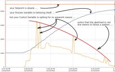
keep in mind that we can't see your system - but based on the graph below, I'd be willing to bet (pocket change only) that:

(a) either SOMETHING is writing into your PIDE parameters behind your back ... or ...

(b) SOMETHING is disturbing the way your PIDE gets "triggered" into execution ...

can you post the ENTIRE project file? ... (ACD extension) ... if it's too large, try doing a File Save As and save it as an L5K file ... either way, you'll have to zip the file to post it - but we'll be glad to take a look at it for you ...

.

PIDE_spikes.jpg
 
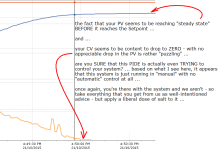
a few more thoughts ... see the notes below ...

I strongly recommend that you post your ENTIRE project file ... there's something going on here that's not making sense ...

.

PIDE_in_control.PNG
 
Last edited:
There are several issues to deal with.
1) The control valve is oversized. A smaller valve that opens more gives better control.
2) The trends do not show enough points. There are spikes in the CV that don't follow the PV, as the CV seems to be compressed by the historian.
3) The PID is trying to control a valve when it shouldn't, so you've adjusted the gains to compensate. With proportional control, any time the PV increases, the P proportion of the control calls for the valve to open. But you don't want the valve to open during normal conditions, so you've compensated by having so much integral gain. The integral gain portion overcomes the proportional to keep the valve close during normal conditions. Thus you are using mostly Integral for control, when Proportional would work much better.

If you didn't have a PLC and had to control the valve manually, would you open the valve when the pressure went from 2000 to 2200? Or would you keep the valve closed until it went over a much higher level (since 9000 is OK), or saw the pressure ramping up?

You might want to try keeping the PID in 'hold' until it reaches a higher PV, like 6000 or 8000. Use a smaller Prop Gain, use a much smaller I Gain (or even eliminate it), and use a smaller Derivative (or eliminate it). This way when you get a small swing in pressure you don't open the valve and waste gas. You would only remove the hold when there is a process excursion. After the excursion is over, the valve is closed, and the pressure is down, then put the PID back in 'hold'.
 
The I-PD will only jump if the PV jumps. The PIDE will jump if either the SP or the PV jumps.


Funny, the graphs you show look like there is little if any noise on the PV signal. Perhaps the data sampling is missing some of the noise or it is filtering it iout.


I would use a min or max function to capture spikes and record them so you can see if the PV signal is really that noisy. If so I would check to see if there is a correlation between the "noise" and other equipment starting up and try to reduce the "noise".

It appears your process is very slow. You could put a low pass filter on the PV. You could also put a sanity check on the PV. For instance, in motion control I know that the motion can only be so fast. If I get an unrealistically big change in position feed back we ignore it and estimate what should be happening based on our control output.

BTW, here are some of the spread sheets I made years ago. Some use PID and other use I-PD. I think all are the incremental form like the PIDE uses.
http://deltamotion.com/peter/xls/T0P4.zip
The whole directory is here
http://deltamotion.com/peter/xls/

We will almost never be changing the SP so I-PD is not really any use.

There is no noise on the PV signal, the trend may have compression enabled though.

The project file is absolutely gigantic with 100s of IO so I've deleted pretty much everything other than the flare controller PIC022

https://dl.dropboxusercontent.com/u/1428435/example.ACD

There are several issues to deal with.
1) The control valve is oversized. A smaller valve that opens more gives better control.
2) The trends do not show enough points. There are spikes in the CV that don't follow the PV, as the CV seems to be compressed by the historian.
3) The PID is trying to control a valve when it shouldn't, so you've adjusted the gains to compensate. With proportional control, any time the PV increases, the P proportion of the control calls for the valve to open. But you don't want the valve to open during normal conditions, so you've compensated by having so much integral gain. The integral gain portion overcomes the proportional to keep the valve close during normal conditions. Thus you are using mostly Integral for control, when Proportional would work much better.

If you didn't have a PLC and had to control the valve manually, would you open the valve when the pressure went from 2000 to 2200? Or would you keep the valve closed until it went over a much higher level (since 9000 is OK), or saw the pressure ramping up?

You might want to try keeping the PID in 'hold' until it reaches a higher PV, like 6000 or 8000. Use a smaller Prop Gain, use a much smaller I Gain (or even eliminate it), and use a smaller Derivative (or eliminate it). This way when you get a small swing in pressure you don't open the valve and waste gas. You would only remove the hold when there is a process excursion. After the excursion is over, the valve is closed, and the pressure is down, then put the PID back in 'hold'.

Yes the control valve is massively oversized, we have had to limit it from 0-15% as above 15% it exceeds the flare capacity, unfortunately they will not be replacing the valve (incorrectly supplied), this means control is ordinary however it does not need to be that good and the pressure can hunt/fluctuate without much issue as it is hardly ever used.

Setting the PID to halt when the PV is x% below the SP is probably the best idea so far.

a few more thoughts ... see the notes below ...

I strongly recommend that you post your ENTIRE project file ... there's something going on here that's not making sense ...

.

The output may have been disconnected from the process at that stage (8 months ago) however the point I was trying to demonstrate was the CV opening when it shouldn't. The reason pressure reached steady state is the PID is not meant to control the process, the downstream process is controlling it almost 99% of the time and there are other upstream controllers controlling the inlet pressure, this PID is only if everything fails and the gas has to go somewhere (to atmosphere).

Think of this PID as an override, most of the time the PID is not in control of the process, only if the pressure gets near the SP is it in control and it should start controlling. If it isn't in control (eg large negative error) it should not open the CV
 
Last edited:
I see your issue now. I read through your initial post too quickly.

It really surprises me that the incremental form of the PID used n the PIDE instruction doesn't handle your case more elegantly, or at least have some hooks in place to more directly handle the case.

It would appear something is replacing the PV signal into the PIDE instruction for some period of time. As Ron pointed out, the size of the spikes are proportional to the size of the error. It almost looks like , for some time, the PV is being set equal to the SP. This creates a step proportional to the difference between the SP and the PV until the PV is again allowed to assume its normal value, at which point the CV steps back down. I'm not sure if there is a control bit in the PIDE structure that will do this but it certainly looks like that is happening.

I think you are on the right track with putting the instruction into some non-controlling mode programatically. I would make sure the PV<SP AND Cv=0 before doing that, though. That would allow for some motion around the setpoint but would prevent any response as the PV rises from below the SP until the PV crosses the SP.

Keith
 
"PV is being set equal to the SP. "

This happens if the loop is put into manual or there is a CV/PV fault I believe, I vaguely remember a setting that makes it do this.

If this was happening that regularly we would see PV spikes and point failure alarms though it is worth investigating.
 
Originally posted by rollex:

This happens if the loop is put into manual...

If the loop is put into manual the CV wouldn't respond to the PV when it returns to auto I don't think. This would have to be something that is happening without the PIDE instruction's knowledge.

Are you the first person to work on this program? Setting the PV=SP if PV<SP would be a tricky way to prevent the instruction from responding to changes in error until the PV > SP.

Keith

There is definitely a setting that can set SP=PV when in manual mode, this way when the loop returns back to auto there is no bump or windup. This is a built in function and simply a tickbox within the PIDE popup though now that I think about it it will cause a change in error when it happens which could cause the behaviour I've seen.

PVTracking
BOOL
SP track PV request. Set to cause SP to track PV when in manual mode. Ignored when in Cascade/Ratio or Auto mode.
Default is cleared.
 
Last edited:
Originally posted by rollex:

...it will cause a change in error when it happens which could cause the behaviour I've seen.

You can test this to confirm, but I don't think this is the issue. This is an action that the PIDE instruction knows about. Part of the switch from manual to auto would be to babysit the fact that an error will be present and to effectively ignore this step. Even if the instruction didn't ignore the change in error, the step would only be in one direction when the instruction is re-enabled. It wouldn't move back a short time later. If, however, the equating of PV to SP occurred OUTSIDE of the PIDE instruction it would have no knowledge of this and would respond to the change in error as you have seen.

Then again, I would have thought that that instruction would have protected against a positive error delta creating a proportional response in your case also but that is obviously not the case. And people look at me funny when I say I write my own PID functions.

Keith
 
Last edited:

Similar Topics

I've read 1756-rm006 and I can't fully understand what the difference is between manual and operator control mode. I'm used to "auto" and...
Replies
11
Views
4,155
Hallo Everybody, Did anybody from you had a sample how to do pump control with flow sensor ??? I only did temperature control with pide yet...
Replies
4
Views
4,580
Hi Guys! I'm having problems getting the AB PIDE block to actually regulate anything, it seems to be the same problem everytime I try to use one...
Replies
23
Views
6,901
Hi, I have a ControlLogix system with 1756-IF16 analogue inputs. I can't scale the inputs at the card as there is a requirement to facilitate...
Replies
14
Views
386
Dear community, I am trying to find a tool for Allen-Bradley PLCs similar to SiVArch for Siemens PLCs to automatically generate faceplates and...
Replies
0
Views
108
Back
Top Bottom