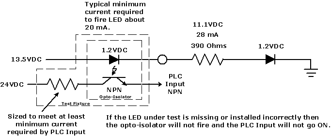
I've got 2 LED circuits I need to test on my assembly line for my customer. I've come close but need better or different ideas. One circuit is a 390ohm resistor in series with 2 LED's powered by 13.5 VDC, the other is one LED with 910ohm resistor.
Customer's concern is the LED's not being installed on the circuit board or being installed backwards. No vision to be used here or analog card either since there is already 2 machines built previously that we would like to integrate this checking feature into for them without adding much on.
The basic idea I've had from the beginning is to insert a relay coil in series with everything else so if the LED conducts the relay coil will turn on, giving me a way to also trigger a PLC input that says the circuit is OK. The problem is I have not come up with a relay coil that has the correct characteristics to work in the circuit. And any attempts to "modify" the coil resistance by putting a resistor in series or parallel with the coil would only get me further away. I had one sort of working earlier but it is not reliable. 12VDC coil with 3200ohm resistance only has about a 7V drop across the coil and the specs. say it will reliably turn on at 80% and guess what - they were right. It hardly ever turns on.
I wish I had some solid state relays here or information about them. I can't find it. I know there is nothing mechanical in there and that the switching is triggered by an LED or optical circuit but since there are different voltage coils available I can't believe it would gain me anything over a mechanical relay coil as far as the characteristics go because there is probably another resistor in there to limit current to the optical or LED circuit. Anybody have some good information on SSRs?
The customer suggested running an output from the PLC through the circuit into an input to the PLC. I know that won't work because the LED will never conduct without turning it on with some voltage but it may prompt some other ideas.
I keep getting stuck on my first idea and can't find a relay that will work in my circuit and have not thought of any other ideas as of now.
I would appreciate any ideas you may have.
thanks


