Boiler Two Element Control

widelto

Member
Join Date
Jul 2005
Location
Barranquilla, Colombia
Posts
3,392
HI All :

We have a boiler that can produce up to 75000 lb/hour, this boiler has two CompactLogix Plcs from Allen Bradley , one is used for burner
management and the other one is used for combustion control.

This system was designed and commisioned by a contractor, I am trying to learn boiler control and I found the there are three way to control a boiler:
Single, 2 and 3 element control.

Attached you will find several pictures as follows:

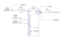
RS5000 Drum level control , this the way drum level is configured and working right now, this is done thru and AOI. This system is a Single-Element Control.

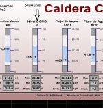
Drum Level, this is our scada picture of level control, numbers (regulation) are ok. You can see last 30 minutes values, max, min and mean values.

Two Element control, I found this figure from a book and I would like to change my control to a new one like this.

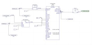
New control, this is the way I would like the new control to be implemented.

My doubts are the following:

I would like to know how to put my steam flow value into the equation (steam flowmeter is already installed and working properly), I do not see how my flowmeter data (4-20 mA)or lb/hour can be squared rooted as two-element control suggest. In other words, I want to know how to handle K Factor in my "New Control" figure.

Do I need to use a scale factor in order to mix (sum) data from level controller and data from steam flowmeter ??

I also read that steam flow data can be used as a feedforward into the PIDE control. Same question as before Do I need to extract squared root from steam flowmeter and then scale it to be entered as a feedforward into my PIDE ??

Regards,

william
Rslogix 5000 Drum level control.JPG Drum Level.JPG Two elements Boiler Control.JPG New Control.jpg
 
Regarding the square root: refer to the Navier-Stokes equations, which reduce to Bernoulli for to-first-order incompressible fluids, IIRC.

It is unlikely that the [FE 1] (flow element?) is an actual steam flow-meter i.e. unlikely that its output is linear with flow-rate; I suspect any flow-meter based on mass flow techniques would be very expensive at typical pressures and temperatures of steam. [FE-1] more likely measures differential pressure across an orifice plate, flow nozzle or other flow restriction, as suggested by the venturi-like icon used in the P&ID diagram. And as it is also unlikely that the flow is laminar, the differential pressure drop across the flow element will be linear with the square of the flow-rate, which is why the square root extractor is in the measurement chain.

This is all to first order, of course.

Perhaps the P&ID could rename [FT-1] to [dP-1] and change the annotation to "Differential-Pressure transmitter."

This is momentum transport; cf. "Transport Phenomena," Bird, Steward and Lightfoot.
 
Last edited:
HI All :

RS5000 Drum level control , this the way drum level is configured and working right now, this is done thru and AOI. This system is a Single-Element Control.

It seems to me that this diagram (Rslogix 5000 Drum level control.JPG) indicates that 3-element control is currently configured. (Assuming FT100101A_SCL is water flow, FT100101B_SCL is steam flow, and Nivel_Lazo_Primario is the output of the level controller).
 
...
Do I need to use a scale factor in order to mix (sum) data from level controller and data from steam flowmeter ??


With the two-element control arrangement in [New Control.jpg], yes; an un-scaled steam flowrate (or even a square root of differential pressure) cannot be added to another number (the PID output, in this case) to yield a speed reference in Hz.


The control system will always need to do some scaling somewhere.


As noted in another thread, converting to engineering units (lb/h i this case) as soon as possible i.e. in the PLC usually makes much of this simpler. But if the process does not measure the feedwater flowrate, then an approximation of the conversion between lb/h and Hz is still needed to do the feedforward.


The difficulty might be determining a scale factor K*, that works for all conditions, to convert from lb/h to Hz; it will essentially always have some error, and that error will change as conditions change, but the Integral action in the feedback PID will correct for that error i.e. the level error communicates any changes in the error in K.


That said, tose are all second-order effects, so if you get K close enough, then I expect two-element control will be satisfactory.


I also read that steam flow data can be used as a feedforward into the PIDE control. Same question as before Do I need to extract squared root from steam flowmeter and then scale it to be entered as a feedforward into my PIDE ??


I am not sure what is meant by "feedforward into the PIDE control," but again yes, you will always need to do some scaling somewhere with two-element control.


Try the passing the search terms [feedforward with feedback trim] to The Google.


Is there a flowmeter on the feedwater?


* the scaling factor K includes the flow element's flow coefficient C that converts from differential pressure (PSI or bar or perhaps even raw counts) to lb/h; so [K = C * f2Hz], where F2Hz converts flow (lb/h) to Hz.
 
Last edited:
I don't understand. Why is there a need to use a square root if you already have the steam flow? I understand the steam flow is proportional to the square root of the pressure drop but it looks like the steam flow is provided. If you have the steam flow in lbm/hr then K needs to convert lbm/hr to level/hr. The steam flow reading should be used like a feed forward. The PID is just a trim. The set point is a level so eventually the out put of the PID must be scaled to level / hr.


What can make this tricky is the conversion from mass to level. Differences in temperature and pressure can cause the density of the water to change. This shouldn't be a problem if the load doesn't change.
 
Perhaps the P&ID could rename [FT-1] to [dP-1] and change the annotation to "Differential-Pressure transmitter."
P&ID's have historically used functionality, not technology, as the basis for identifying the field instrument, which is why in this case, it is an FT, not a PT.

It is a DP PT (transmitter), but it functions as a flow transmitter.

Vortex meters are used as steam flow meters but do not utilize a separate flow element, like DP does.
 
You measure level (%), feedwater flow (m^3/h Flujo de Aqua), and steam flow (Kg/h Flujo de Vapor) as indicated in your Drum Level jpg. It would seem you have all the info to do 2 or 3-element control. (A long time ago I did 3-element control on a PLC5 in ladder).

In boiler-control-speak, 2-element level control is simply PI control with feedforward; the 2 ‘elements’ are level and steam flow. For the PIDE instruction, you assign some scaled version of the steam flow to the FF pin of the level controller’s PIDE block. The scaling should be done in such a way that a change in steam flow approximates a change in feedwater flow (as effected by a change to the vfd). I think your confusion about square root is simply that it appears in the generic Two elements Boiler Control.JPG diagram; disregard the square root and simply use a scaled value of whatever is presented on your Drum Level jpg. Of course, you’ll want to verify proper PIDE behavior (scaling, auto-manual/manual-auto transitions, windup/range behavior, error handling, etc) before implementing.

3-element control uses the above 2-element, but the output of the level controller cascades to a feedwater flow PI controller. In this instance, scaling of the steam flow should be weighted such that incremental changes in steam flow offset equal incremental changes in feedwater flow (setpoint). 3-element control has the effect of linearizing the controller over a wider operating range and compensates for disturbances that may otherwise affect water flow regulation. Assuming the pump/vfd are dedicated to this individual boiler, the latter consideration might not be a factor.

As an aside, based on the info on your Drum Level jpg , I’m assuming you have some continuous blowdown in your system due to the mismatch between feedwater and steam flow. Feedwater in = steam + blowdown (not depicted). Blowdown removes accumulated/concentrated water-borne minerals/solids from the boiler. Feedwater density is about, though somewhat less than, 1000Kg/m^3, so blowdown would be under 10% of feedwater flow - fine (So, the dynamic numbers on your Drum Level jpg are plausible although there’s something not right with the static scale on the steam bar graph).
 
Hi all:

I´m trying to learn step by step, initially i want to covert my system to two-element contron and finally It will be a 3-element control.

I do have a waterfeed flowmeter, it´s working fine. Vortex technology.

@Drbitboy:
I am not sure what is meant by "feedforward into the PIDE control," but again yes, you will always need to do some scaling somewhere with two-element control.

Drbit, PIDE instruction has an input called feedforward, thru that input i want to enter steam flowmeter data into my AOI. PIDE is part of AOI "PID_Control".

Is there a flowmeter on the feedwater?
yes, I want to use this flowmeter when I change to 3 control element , first i want to know how 2-element work out.

@Peter Nachtwey:
I don't understand. Why is there a need to use a square root if you already have the steam flow? I understand the steam flow is proportional to the square root of the pressure drop but it looks like the steam flow is provided.

Peter, I agree with you. The info I got was from siemens webpage, maybe they need to change it, in my case my flowmeter use vortex technology.
My flowmeter units are kg/hr.

If you have the steam flow in lbm/hr then K needs to convert lbm/hr to level/hr. The steam flow reading should be used like a feed forward. The PID is just a trim. The set point is a level so eventually the out put of the PID must be scaled to level / hr.

Peter, that´s interesting, please elaborate on it.

What can make this tricky is the conversion from mass to level. Differences in temperature and pressure can cause the density of the water to change. This shouldn't be a problem if the load doesn't change.

Peter, one of the problems and the main reason to try to change my control is that load changes too much. My worst case scenario is that load could be so small and the boiler protects itself and turns off.

@Danw:

P&ID's have historically used functionality, not technology, as the basis for identifying the field instrument, which is why in this case, it is an FT, not a PT.
It is a DP PT (transmitter), but it functions as a flow transmitter.
Vortex meters are used as steam flow meters but do not utilize a separate flow element, like DP does.

Dan, As I mentioned my flowmeter is using vortex technology. Thanks.

@jamesau:
In boiler-control-speak, 2-element level control is simply PI control with feedforward; the 2 ‘elements’ are level and steam flow. For the PIDE instruction, you assign some scaled version of the steam flow to the FF pin of the level controller’s PIDE block. The scaling should be done in such a way that a change in steam flow approximates a change in feedwater flow (as effected by a change to the vfd). I think your confusion about square root is simply that it appears in the generic Two elements Boiler Control.JPG diagram; disregard the square root and simply use a scaled value of whatever is presented on your Drum Level jpg. Of course, you’ll want to verify proper PIDE behavior (scaling, auto-manual/manual-auto transitions, windup/range behavior, error handling, etc) before implementing.

James, that sounds great. It´ll take several cups of good Colombian coffee (by the way) to try to decipher the whole thing. Thanks.

As an aside, based on the info on your Drum Level jpg , I’m assuming you have some continuous blowdown in your system due to the mismatch between feedwater and steam flow. Feedwater in = steam + blowdown (not depicted). Blowdown removes accumulated/concentrated water-borne minerals/solids from the boiler. Feedwater density is about, though somewhat less than, 1000Kg/m^3, so blowdown would be under 10% of feedwater flow - fine (So, the dynamic numbers on your Drum Level jpg are plausible although there’s something not right with the static scale on the steam bar graph).

James, I also read that ratio between feedwater flowmeter data and steam flowmeter data is very usable , I want to take advantage of it . I will continue reading and learning today until i try to make my first attempt to make any change. Your info is valuable, thanks again.

Thanks all , you are the best, and by the way I wish you all a merry christmas and a happy new year.

Regards,

william
 
@Drbitboy:
I am not sure what is meant by "feedforward into the PIDE control," but again yes, you will always need to do some scaling somewhere with two-element control.

Drbit, PIDE instruction has an input called feedforward, thru that input i want to enter steam flowmeter data into my AOI. PIDE is part of AOI "PID_Control".

Is there a flowmeter on the feedwater?
yes, I want to use this flowmeter when I change to 3 control element , first i want to know how 2-element work out....


Sorry, I did not understand that the image with the square root function was from this web page (https://instrumentationtools.com/two-element-drum-level-control-system/) about one-, two-, and three-element control, and it is not a diagram of your system. So as you noted, you do not need the square root.


Also, since you do have a flowmeter on the feedwater, you can go direct to three-element control.


Either way, it sounds like you are trying to combine the PID and SUM (Σ) blocks of your [New Control.jpeg]: New Control.jpeg, using the FF input of the PIDE


And the question is about what value to use for [K] in that scale block to the that PIDE [FF/Inpu_FF] input (from here (page 9) and here) of the PIDE block, specifically these:

zzz.png
xxx.png

Also, seeing that the OP wants to first try two-element control (PIDE CV, or CVEU, goes directly to VFD frequency speed reference, via another scale block), and then after that to try three-element control (PIDE CVEU cascades to SP of feedwater flow-control loop), it might make sense to choose lb/h for the CVEU units, and then the PIDE does not have to change between two- and three-element experiments.

However, as PeterN noted, it could be level-units/h would also make sense, presumably to simplify tuning the controller.

Anyway, whatever is chosen, a reasonable starting point would be to assume everything is linear, and multiply by unity to figure out what the values should be at each connection between instructions (PIDE.Inp_FF, PIDE.CV, PIDE.CVEU, VFD.SpeedRef, ...).


So the boiler nominal (maximum?) steam rate is 75,000lb/h, so let's say the VFD/motor/pump is sized for twice that at 60Hz, so 60Hz = 150000lb/h = 100% CV.


62.43lbwater = 1ft**3-water at ambient temperatures, say half that to account for elevated temperature and bubbles in the liquid in the tank, so 31.21lb = 1ft**3, or 1 = 1ft**3/31.21lb, so

  • 75000lb/h * 1 = 75000lb/h * (1ft**3/31.21lb) ~ 2400ft**3/h.
  • 100%-CV = 60Hz-pump = 15000lb/h ~ 4800ft**3/h

Thinking about what happens if the feedwater pump is lost, it would be nice to have some residence time in the drum, 1 minute is too little, 100 minutes is too much, say 10minutes from half-full to empty, 20minutes for the entire drum volume,


  • 20min * 1 = 20min x (1h/60min) ~ 0.33h
  • 2400ft**3/h * 0.33h ~ 800ft**3 for the drum volume

(9ft)**3 = 729ft**3, so say cylindrical drum is 10ft long with its axis horizontal, so its volume (ignoring drum heads) is


  • 800ft**3 = 10ft * PI * R**2 ft**2
  • R = sqrt(800 / 10 / pi) ~ 5ft.
So with the drum half full, there are

  • 5ft * 2 * 10ft = 100ft**2 of area with the drum at half-full, so 100ft**3/ft-level
  • 48000ft**3/h / (100ft**2) = 48ft-level/h
so
  • 100%-CV = 60Hz-pump = 150000lb/h ~ 4800ft**3/h = 48ft-level/h
========================================================================


Summary


Multiply by 1, i.e. (ignoring the level/h approach)


  • The input to Inp_FF is scaled to CV%, to 150000lb/h is 100%, so divide steam flow by 1500, i.e. scale (multiply) by 0.67e-03.
  • Set the CVEU output to be 1500000lb/h at a CV of 100% in the PIDE (Cfg_CVEUMin=0; Cfg_CVEU=150000).
  • For two-element control, scale the CVEU value from the PIDE so 150000lb/h is 60Hz at the VFD, so multiply CVEU by 60/150k = 0.4e-03 between the PIDE and the VFD speed reference output.
  • For three-element control, the CVEU value from the level PIDE can be cascaded directly to the feedwater flow control loop.
Caveats

  • This is only an example based on back-of-the-envelope estimates of the actual process
    • Ignore the residence time calculations above,
    • Substitute the actual drum dimensions
  • The surface area of the water in the drum may vary if the drum does not have vertical sides, so you are on your own for tuning the level PIDE.
  • It is unlikely that that there are no errors in the calculations above, so check your math!
 
Last edited:

Similar Topics

I am implementing boiler 3 element control on Compact logix.. can any body tell explain me control philosophy when three element is selected then...
Replies
3
Views
2,829
Hi guys..... Someone can provide a sample code for Simatic S7-300 (CPU315 DP/PN)about the system control to manage in the boiler the drum level...
Replies
0
Views
3,459
Hi all, I'm currently doing this 3 element control for boiler water level. The 3 elements were water level, steam flow and feed water flow. I...
Replies
7
Views
8,326
Hello, I have problem i'm working on boiler plc, but i get to the problem that i can't solve myself. I have problem with material gate. I need to...
Replies
2
Views
356
hi everyone im using OPERATOR PANEL SPOT PLUS 150 35W 24VDC AUTOMATA ID42003 (as hmi system) and automata optispark controller to control and...
Replies
8
Views
2,415
Back
Top Bottom