Can Crusher Progarm

saintmetal10

Member
Join Date
Jun 2012
Location
Rawalpindi
Posts
8
Hello!
I am making a can crusher controlled by OMRON PLC. I have CJ1M CPU 12 and CPM2A CPU available. I prefer to work on CPM2A. I am new to OMRON PLCs and have many problems regarding programming in CX Programmer.
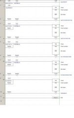
I have made this program attached here with the message. The problem I am getting is that, If I put a normally closed contact before a Delay Timer instruction as used in this program the timer keeps on counting over and over again and it does not energizes the coil attached to it in the next ladder.
Would be grateful for any kind of help as I'm really short on time.
 
Last edited:
I think your problem is using inputs instead of work bits. I have worked with CP1's, and 10.00 is an input. Try using W10.00 - i.e. make it a work bit. Your actual outputs probably start at 100.00
 
I think your problem is using inputs instead of work bits. I have worked with CP1's, and 10.00 is an input. Try using W10.00 - i.e. make it a work bit. Your actual outputs probably start at 100.00
The CPM2A kit I have available has 3 input channels and 3 output channels. The inputs range from 0 to 15 (16 inputs for each channel) and outputs range from 0 to 7 (8 outputs for each channel).
I am using the first input channel and first output channel. And 10.00 is not an input here. It is the first output and I have tested it with the PLC.
 
I can't open your program for some reason. If you use a normally open
contact, when that contact closes the timer will begin timing, then
time out based on the preset, and then the timer contacts will change
state. The timer will not reset until the contacts preceding the timer
re-open. It is OK to use direct input addresses.

example: from CPM1A


0.00
-----| |-------------TIM--
001
#50

TIM001 10.00
-----| |-------------( )--

Your NC input condition must be opening and reclosing immediately
after the timer times out?
 
Last edited:
I can't open your program for some reason. If you use a normally open
contact, when that contact closes the timer will begin timing, then
time out based on the preset, and then the timer contacts will change
state. The timer will not reset until the contacts preceding the timer
re-open. It is OK to use direct input addresses.

example: from CPM1A

Input Addr.
0.00
-----| |-------------TIM--
001
#50

Output Addr.
TIM001 10.00
-----| |-------------( )--

Your NC input condition must be opening and reclosing immediately
after the timer times out?
I am making the timer setup just as you stated here. I have attached the whole code in PDF format for you to see. Now you can deduct what the problem is.
 
Check your manual for assigments. Notice your timer has the prefix 'T'. I think your imputs should have the prefix 'I' and your outputs should have the prefix 'Q'.
 
Your addressing is correct, however your programming is not, still
looking at it, but it appears you need holding circuits around your
timer input instructions because you are currently turning them off
with outputs as your program progresses.

Also, you use two different output addresses to represent the on/off condition
of one output. (10.01 gate down motor on/10.02 gate down motor off).
Both addresses are the same device!

Your program compiles with zero errors, zero warnings, correct?
 
Last edited:
Your addressing is correct, however your programming is not, still
looking at it, but it appears you need holding circuits around your
timer input instructions because you are currently turning them off
with outputs as your program progresses.

Also, you use two different output addresses to represent the on/off condition
of one output. (10.01 gate down motor on/10.02 gate down motor off).
Both addresses are the same device!

Your program compiles with zero errors, zero warnings, correct?
Sorry I didn't get the thing about holding circuits as I am new to OMRON PLC programming.

Yes I get your point here. The thing is, in my program (Compiles with zero errors, zero warnings, YES!) I will use the following output addresses from it in the real time PLC use:

1. 10.01
(Gate down motor ON, I have used 10.02 just to turn off the motor after the 2 second interval, as I can't make a timer like this and also as far as I think there are no timers to do that particular operation in CX-Programmer as they were in Simatic S7)

2. 10.03
(Gate up motor ON, again the same case here for 10.04)

3. 10.05
(SV forward pair ON, 10.06 used just to turn the Solenoid Valves (SV) OFF after the specified time, same operation as above)

4.10.07
(SV backward pair ON, same again for 10.08)

Program compiles without any errors and warnings. As I turn my Main Switch (0.00) ON the program runs and is stuck on Timer 0001 which keeps on counting again and again and never energizes 10.02. So the rest of the program also doesn't run.

It would be a great favor if you can take the 5 minutes to write the program and see the simulation results for yourself and solve the problem I am having here. Cheers!
 
I would welcome any kind of help from anyone as tomorrow is the last day of my project submission, all the hardware is set and interfaced with PLC. Its just that these small errors in program are ruining it so as soon as they are omitted, here I am with my project ready.
 
Refer to your pdf;

10.02 never turns ON because:
-you use 10.02 to turn OFF 10.01
-which turns off TIM0001
-which turns off 10.02, as soon as it comes on.

The output 10.02
-might chatter
-might never appear to come on
-might appear to be on
-all bad things

If I were to write programming guessing what your trying to do,
it might look like this. Notice the holding circuit in parallel
with the timer input conditions. Also since 10.00 and 10.09 do
not appear to be physical outputs, I used internal relays 5.00 and
5.01 respectively. Also I eliminated your dual ON/OFF output
addresses in favor of one output, which is turned on and off.
Also you should have a --(END)-- instruction in/as your last rung.
I also used NC IR relay contacts in each timer with
holding circuits to deenergize all outputs at the end of the
cycle, in which case you would have to turn your main switch
to start the cycle again.

CANCRUSHER.jpg
 

Attachments

  • CanCrusher.zip
    232.7 KB · Views: 27
Last edited:
Refer to your pdf;

10.02 never turns ON because:
-you use 10.02 to turn OFF 10.01
-which turns off TIM0001
-which turns off 10.02, as soon as it comes on.

The output 10.02
-might chatter
-might never appear to come on
-might appear to be on
-all bad things

If I were to write programming guessing what your trying to do,
it might look like this. Notice the holding circuit in parallel
with the timer input conditions. Also since 10.00 and 10.09 do
not appear to be physical outputs, I used internal relays 5.00 and
5.01 respectively. Also I eliminated your dual ON/OFF output
addresses in favor of one output, which is turned on and off.
Also you should have a --(END)-- instruction in/as your last rung.
I also used NC IR relay contacts in each timer with
holding circuits to deenergize all outputs at the end of the
cycle, in which case you would have to turn your main switch
to start the cycle again.
I checked and ran the code. It is doing what I intended to do. So thanks a lot for that. I will check it on PLC today.
While you are at it can you also make the whole operation to continue in cycles as long as the main switch remains ON. Thanks in advance!
 
For continuous cycling you could;

-Delete the holding TIM004 NO contacts and branch from rung 9.
or
-Add NC 5.01 contacts in series with rung 9, (copy & paste)
as in the other rungs.
 
You're Welcome.

I was wondering if you (or any other poster) could tell me what
program/method you use to create a pdf of ladder logic? I have
a program that uses the print function from within the application,
but it doesn't produce a pdf like I see on this site. I had to create
a picture (.jpg) file of the ladder logic and then create a pdf
from the picture using the print function, to make the logic appear
unbroken and without adding a lot of clutter added by the print funtion
of CX Programmer. Doing so produces an unessasarily large pdf file
size. How do you do it?

Thanks
 
JRB,

There are a lot of free pdf creator software available on the net. You may install one of them or go for a full fledged Adobe writer.

One of the free ones I use is 'Cute PDF. After installing it, you will have an option of printing to it in your print box, then just follow the instructions to which folder to print it, I mean create a pdf copy.

Regards
_______
 

Similar Topics

I would like to try and build a aluminum can crusher with a small plc controlling it. I would like to be able to hold a wal-mart bag full of cans...
Replies
20
Views
18,573
dear allwe are having a machine.plc used in this is S7 400.i am not able to open the blocks of that program and machine manufecture not in...
Replies
0
Views
1,654
Back
Top Bottom