Can't understand the configuration of a 1771-IFE Allen Bradley Module

Frelecing

Member
Join Date
Oct 2010
Location
Uruguay
Posts
73
Hi:

I am trying to understand the configuration of the analog inputs from a PLC 5-20. It is an 1771-IFE/C module, and it's
using all the 16 channels. I have the Analog Input User Manual that is in http://samplecode.rockwellautomation.com/idc/groups/literature/documents/um/1771-um663_-en-p.pdf

The program has a BTW instruction to configure the Module which is located at Rack0 Module 0 Group4. So the BTW is like this:


Rack -----------000

Group ----------4
Module ---------0
Control Block --N7:10
Data File ------N7:36
Length ---------16
Continuous -----No


The BTR goes like this:


Rack -----------000

Group ----------4
Module ---------0
Control Block --N7:25
Data File ------N7:112
Length ---------22
Continuous -----Yes

To begin with I don't understand the chart in page 39 (4-7) of the manual, where it says that if I want to use 16 channels I have to do a BTW instruction of length 37 and a BTR of 20.

In my PLC I AM using the 16 channels (i know because it is working) and those lenghts do not match with the ones in the chart. There is something I am not getting...

Secondly: The Control Block of the BTW is N7:36, This Block goes like this in Hex/BCD:


Offset..0....1....2....3....4....5....6....7....8....9

N7:30 ..0....0....0....0....0....0....0....0....2C30.0
N7:40 ..0....0....4095.0....4095.0....4095.0....4095.0
N7:50 ..4095.0....7....C..............................

Because of the operations it uses then on the read data I guess my application doesn't uses scaling, so I don't understand why it defines the min/max values for some channels, and not for all of them or none at all.


Obviously I'm not understanding this scaling feature, Can some of you help me?

Thank you very much for your time.
 
can you post your complete RSP file? (you'll have to zip it first - forum rule) ...

the help we give you can be a lot more detailed if we can see that file ...

just to make sure ...

the system IS running OK ... you just want to understand what you're seeing? ... is that correct? ... or do you really have some sort of operational problem? ...
 
Thanks Ron:

Yes, the program is working OK, but I have to make some changes now, and I need to understand this.

Here I attached the file you asked me. Note that there are many Analog Input/Output module, I just didn't mention it at first because I only need to understand that one.

Some time ago I had the same problem with another PLC but I could solve the problem without facing this details. Now I am not that lucky and besides it's something I want to understand. Because if I have to design a prgoram from scratch I would be very confussed.

Once I get that, the rest is almost the same. Thanks again!
 
In my PLC I AM using the 16 channels (i know because it is working) and those lenghts do not match with the ones in the chart. There is something I am not getting...

I think that if scaling is not needed for ALL 16 channels, then the file lengths can be something other than 20 for BTR and 37 for BTW.

If scaling is not selected, the module requires specific minimum BTR file lengths for the number of channels used. The BTW file length can be set to 3 words.

On page 4-8 of the manual, an example is given where only a length of 5 words is sent to the BTW to configure the analog input module (no scaling on any channel, no filtering, no sampling). The number of words needed to configure a module depends on how the module must be configured. The more options needed, the more words are needed to perform the configuration.

If a write block of five words, with all zeroes, is sent to the Analog Input Module (cat. no. 1771-IFE series C), default selections will be:

1 to 5V dc or 4 to 20mA (dependent on configuration jumper setting)


BCD data format

no real time sampling (RTS)

no filtering

no scaling

single-ended inputs

 
Last edited:
well, first of all, you've got some serious "overlaps" in the way you're using the N7 data files ...

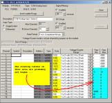
the figure below shows how the module you've asked about is currently set up to be configured ...

notice that the scaling information in the blue highlighted area is almost certainly bogus ...

some of the reason for that is shown in the next two posts ...

important: notice that this SAME data is being written out to THREE analog input modules ... this is questionable ... presumably all three cards are identical – so presumably they should all be able to use the same configuration ... still – this is NOT the way the configuration is usually done ... common practice requires a SEPARATE data file for each module ... so – even if it works, I'd still fix this anyway ...

.

forno_setup.PNG
 
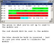
the figure below shows the data which SHOULD be reserved for the configuration of your analog input module ... you're only set up to send 16 words ...

tip: if you've got to fix this, I'd recommend that you create a brand NEW integer file – and start using that file instead of the N7 file for your configuration (BTW) data ... that would be the easiest way to avoid the types of overlaps which are coming up in the next post ...

.

forno_data_file.PNG
 
Last edited:
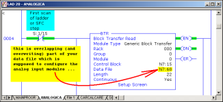
this is ONE instance (there may be more) of where your programming is writing bogus data into the memory area (N7:36 through N7:74) which SHOULD be reserved only for the configuration of your analog input module ...

I hope this helps ... out of time for now ...

.

forno_overlap_1.PNG
 
quick question: are you SURE that all of these channels are still working correctly? - on all three of your analog input modules? ...

I don't doubt it - but that is truly amazing ...

how long has it been since this system has had a "power cycle" or been put in the Program Mode? ...

reason for asking:

you've got this set up to only send the configuration to the modules on the first scan of the program ... so ... maybe the system was fired up once-upon-a-time with a "good" (or at least a "working") configuration - and then it's been chugging along on that data ever since ...

I'd really like to know the story behind this one ... it looks like a classic ...
 
Thanks for all your answers.

For what I see, I'm not the only one confused with this way of configurating the Module.

Ron: I guarantee you this is working just fine, because it's been like this since the year 1998, so I will not touch this delicate piece of history just because, haha...

Lancie: I understand what you say, but this is not the case. It specifies that if you write 5 words with all zeros then the configuration is the default one, but I'm not writing just 5 "zeroed words"...

Ron again: I don't know how long has it been since the last Power Cycle. more than 1.5 years (the time I've been in this company) for sure. But I don't think it is overlapping information becuase I'm only writing from N7:36 - N7:51 and that is not used by any other part of the program.
By the way, how do you see the configuration of the module as you post it on your first attachment?

Well, thanks for your time, and for at least showing me it's not wrong to be messed up with this.
 
here's how to access the "setup screen" ...

http://www.plctalk.net/qanda/showthread.php?p=137747&postcount=7

I'll try to take another look (deeper) into your program this afternoon ...

from what time I've had so far, it looks like only a "few" of the channels on each module are being used ... the others go through some sort of scaling calculations - but I don't see where the scaled values are actually being used in the rest of the program ...
 
But I don't think it is overlapping information

well, the overlap IS there - as shown in Post #7 ... now whether or not the overlap is causing any problems is another story ... in other words, the overlap might not be an issue with the way your system is currently operating - but this is the type of situation that can cause problems ... you need to AT LEAST keep a careful eye on it ...

TIP: start a new EXPERIMENTAL program file (offline) - and try clicking the "Insert Ladder Rungs" button in the upper left corner of the screen shown in Post #5 ... I think you'll find that to be very interesting ...
 
Last edited:
Lancie: I understand what you say, but this is not the case. It specifies that if you write 5 words with all zeros then the configuration is the default one, but I'm not writing just 5 "zeroed words"...
Well, my read on what the manual says is that if you don't need a feature and DO NOT WRITE ANTHING to those words that set that feature, then those words stay at the default value.

What your program does is create a screwed-up mess that looks dangerous and certainly is hard to follow. I think it best to rewrite ALL the words with the values needed, whether 0 or something else, and as Ron says, make sure that you are not using those locations for something else (as your program certainly does).
 

Similar Topics

I have been reading everything I can find on the P_LLS the last 2 days but I am still having trouble understanding how the P_LLS swaps beyond 2...
Replies
9
Views
581
Hello Guys, I have been trying to study a Machine that have Omron 3g3mv VFDs that is controlled by CJ1m CPU and SCU41-V1 communication card. The...
Replies
0
Views
476
On the laser displacement sensor now connected to my PLC, the manual says 4mA=643 and 20mA=64,877. However, I checked with a Fluke, injecting...
Replies
5
Views
890
I'm from a Mitsubishi Q-series background so excuse my ignorance. In Mitsubishi world, in my experience your Mbits (booleans) are just M1, M2...
Replies
20
Views
2,792
Good Evening , I purchased an Avery Weigh-Tronix - ZM301-SD1 to weigh a tote. The loadcell is a FLS -250. Below is the color code and...
Replies
5
Views
1,289
Back
Top Bottom