Color Sorting in Studio 5000

jbilby62

Member
Join Date
Mar 2022
Location
New York
Posts
10
Good afternoon all,

I am working on a college project where we have to sort 3 different color legos. Orange, Black, and Tan. I am using a color sensor with 3 outputs (1 for orange, 2 for black, and 3 for tan) and 3 capacitive photoelectric sensor to detect when each lego is in the eject position for the actuator to push the lego off the conveyor.

My current ladder logic will use the color sensor and move an integer (1 for orange, 2 for black, and 3 for orange) and then wait for the photoeye to detect the presence of the lego. Everything works flawless when the legos come down the conveyor in orange, black, tan orientation, but that will not always be the case. When black comes before orange for example each color is sensed before a lego reaches the eject position. In this case, black is sensed by the color sensor but then since every photoeye reads the lego, the black lego gets ejected down the orange lego chute.

My ladder logic skills are basic but I am assuming some sort of array will need to be used to only fire the corresponding actuator that matches the color sensed. And this is where I am struggling.

Thank you!
 
You need a shift register to do it properly, This would normally require some form of encoder, but a proximity sensor will do on a toothed wheel or if this is not available could use a timed pulse say every 0.1 second (100ms) for test purposes.
The idea is that there will be a pulse say every 10mm of conveyor movement or even greater even 100mm then when the object is detected the appropriate value is pushed into the shift register, pushing the others down the queue.
There have been plenty of posts here regarding this, The shift register would have to be for example if each pulse was 100mm and the conveyor was 4m long then that's 4000/100 = 40 registers long.
The data is shifted every pulse so no parts zero is pushed into the shift register, when a part is detected, the part colour (1,2,3) is loaded into the shift register every pulse pushes it down the shift register.
Let's assume that position 0 is the detect, 400mm down is the orange another 400mm is the black & next 400mm is the Tan, then you do a compare at position 4 for a 1, position 8 for a black & so on.


so see below

this is the shift register & the data
0123456789-----------20------- Register array number
0300020001000300002001000100030002000200030003 Register array
--------P1---------------P2-----------------P3 this is the position on the conveyor for the pushers so when a part is detected that position is compared with the required part value And if the same rejected.
You just need to work out the length of the shift register with reference to the length of the conveyor & how often you need a pulse
You can see that there is a part type 2 at divert P2 (array[20]) so it is rejected.
Here is a simple one using a word shift function not Siemens as I do not have it loaded but others here may help.
 
If the classroom project doesn't have a input for a pulse proxy or encoder then what you could do is shift the register everytime your color sensor changes from 0 to a value.


Move the color value to the first register and then shift it. When a Lego gets to the eject area photoeye look at the earliest register shifted, eject the correct way and zero that register so the next Lego is the next oldest register.


EDIT: to keep track of which register to look at you could count up a counter for each Lego registered and count down one for each eject.
 
It sounds like there is one color-measurement station, followed downstream by three eject stations, is that correct?

the ladder logic and associated data compose a model of the real-world system in place; the reason your code does not work is because the programmed model does not adequately represent what is present in the real world.

let's say the first eject station downstream of the color-measurement station is for orange legos, the second is for black legos, and the last is for tan legos.

Data

  • Alsatian, INT - number of black or tan legos that need to pass the orange station
  • Tan, INT - number of tan legos that need to pass the black station
Logic

  • See Caveats below!
  • When a black lego is detected at the color-measurement station:
    • increment [Alsatian] by 1
  • When a tan lego is detected at the color-measurement station:
    • increment [Alsatian] by 1
    • increment [Tan] by 1
  • When a lego is detected at the orange eject station:
    • IF [Alsatian] is 0, then eject the lego at the orange station
    • ELSE decrement [Alsatian] by 1
  • When a lego is detected at the black eject station:
    • IF [Tan] is 0, then eject the lego at the black station
    • ELSE decrement [Tan] by 1
  • When a lego is detected at the tan eject station:
    • Eject the lego at the tan station
Caveats

  • Each piece of the logic above needs to act on an edge detection
    • e.g. if the color-measurement station detects a black lego over several program scans, you do not wan to add 1 to [Alsatian] on each scan.
    • So the color-measurement station must transmit a 0, or something other than 1 or 2 or 3, between legos
    • You will spend more time on this, i.e. on edge detection, than you will on the rest of the logic
      • But once you have the edge detection working reliably, the rest will be simple
  • Initialization is important
    • If there are legos between the color measurement station and the eject stations when the program starts, this logic will not work, because the model does not adequately represent the real world.
    • you may need a separate input to reset all of the counters, which will require the operator to simultaneously remove all legos past the color-measurement station.
  • This is somewhat analogous to @parky's shift register, but instead of shifting data with conveyor movement as in @parky's approach, this shifts data with lego movement, as detected by the various sensors.
 
Last edited:
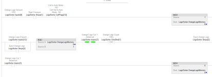
Here is an (untested!) approach to implement the required edgy nature of the logic. The Lego detection at a Lego rejection station may require some debounce to ensure noisy sensors do not generate false edges. The 750ms in the TOF is a number I pulled out of thin air; one would need to know the physical process to select the right value, if any.

Yes, I know the second rung will be unnecessarily subtracting 0 from ALSATIAN on many scans; I don't care.
xxx.png
 
but that will not always be the case. When black comes before orange for example each color is sensed before a lego reaches the eject position.


Does this mean that multiple Lego's will pass the color detector before being ejected?


If one color is detected and ejected before the next Lego is color detected then you will only have one Lego to deal with.


However the above makes it seem that multiple Lego's will be recorded before one reaches the ejection, for this you will have to use a shifting register to log each Lego in your 'area' and eject properly, then clear the ejected register.

Correct. In some cases at most two legos are detected by the color sensor before anything gets ejected. I’m assuming I’d either need a BSR or BSL for each color.
 
Correct. In some cases at most two legos are detected by the color sensor before anything gets ejected. I’m assuming I’d either need a BSR or BSL for each color.


That is just bits, and would require two bit arrays (you don't need an array for the last eject station; it ejects anything it sees because all other colors have been rejected already and never get that far).

Or you can use a single INT FIFO (FFL and FFU instructions) like @parky suggested, to put the current color INT into an array of INTs, or a 0 if the color measurement does not have a lego in front of it, and size the array long enough to represent conveyor movement past the second ejection station, and the orange and black eject stations look at a particular location in that FIFO array to see if the color at that location in the array matches the eject station's color when it detects a Lego.
 
Last edited:
Correct. In some cases at most two legos are detected by the color sensor before anything gets ejected. I’m assuming I’d either need a BSR or BSL for each color.


You would need 3 arrays for bit shifts, and shift all 3 every detection.


As you have a value for the color (1, 2 or 3) you should do a File Shift of DINT's and write the color value as first suggested.
 
Put your color sensor at lane 1. If color is true for Lane 1 then eject Lego into Lane 1. If color is true for Lane 2 then set bit 0 of a INT. Place your first detect PE slightly greater than one Lego length behind the Color sensor. (You'll need to shift that result if lane 2 Legos are back-to-back.) IF INT.0 = 1 and PE1= 1 then one shot and Multiple INT x 2 and Store results in the same INT and OTU bit 2 of the INT. (This will keep your shift bit INT the correct length) Place your second PE Slightly greater than 1 Lego length behind PE1. This will be Lane 2's location. If bit 1 of INT = 1 and PE2 = 1 then eject Lego at Lane 2. The last just ejects all. Because we already removed the first 2 colors. You really don't need the 3rd PE because we only have 3 colors. If you want to use the 3rd PE, you could set up a separate shift INT for Lane 3 and this would allow you to reject any other color off the end of the conveyor into a reject bin. Because they do match one of you color detections. Just make sure you move your color results into an INT you can reset. The Logic for lane 3 is similar to lane two but not the same. See if you can figure it out. Good luck with your project.

The only requirement for system to work is the distance between Legos must be greater the distance between PE's.

I posted this before reading you setup. So, this may not be an option.
 
Last edited:
I have done many systems like this & the only real reliable way is to use some kind of synchronisation i.e. encoder or pulse generator.
Encoders are expensive so a star wheel & proxy will do the job, alternatively providing the conveyor speed does not change then a simple pulse generator like a timer that produces a pulse every X ms. I did a number of strapping machines (existing) but the requirement was that rather than have an operator selecting the strap pattern (there were at least 22 types) the system was retrofitted with star wheels to generate the pulses, for example a pallet would arrive at the input of the strapper, as it entered, there were a number of measurements taken, the length, if it had bottom runners or just blocks, based on this the pallet entered the machine, the strapper had 3 swords that were sent through the pallet i.e. if a small pallet and bottom runners only one sword to guide the strap was fed there were pe's either side of the swords if it saw a blockage then the conveyor would move back/forward to find a gap, try this 4 times if not stop & alarm, if the pallet was without runners then no swords needed so strap fed directly underneath, this after first strap then the pallet was rotated & the same operation would happen to cross strap the pallet, so there were a lot of combinations, small pallet, normal pallet requiring two straps each way, larger, requiring 3 straps but no rotation, very large or double pallet requiring 4 straps, plus if swords or under strap based on runner board or not. so you can see there were lots of combinations all based on measurement and shifting data from infeed to strap area. This system worked well, I was asked to do the same on a similar strap machine, however, this one would not have the star wheel (no idea why but that was the customer's decision), In this case I used a reciprocating timer of 100ms to simulate the pulses, this gave almost as good results.
So providing you do have sensors at the divert stations then it would work well.
One other point, often if you think of the conveyor as the shift register i.e. every location in the shift register is say 200mm of conveyor then where the divert photocell sees the part it may be that the part information could be in two registers of the array, just compare for both & arrange the leading edge of the part sensor to be in a position where the part will be in the centre of the divert.
Another system I did used a bar code reader that read the bar codes, tracked the parts & diverted them based on bar code down one of 17 diverts, this was a very long conveyor so required an array of 2000 registers.
 
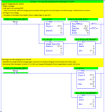
Here is some code using a timed pulse generator to sync the array with the conveyor, this allows for no parts detected so takes care of a missing part that would nock the sync out of the shift as the location sees a "0" when no parts.
here the part type (1,2,3) is loaded into the shift register (Note: I'm not using a shift register as such but a block move function this copies from Array[0] to array[1] & 99 effectively shifting the data by one location, when a part is detected at the divert position with the PE it compares the data in that array with a fixed value i.e. 1,2,3 if for example when the Orange divert PE detects a "1" then it sets the reject, this is held in divert for a time & then releases the divert, you could use the NOT of the PE to reset the diverter i.e. assume once diverted the PE clears.
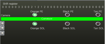
Also attached, is a screenshot of a HMI screen showing it in action note at the orange divert the shift register array word 10 is at a "1" so the PE is covered & the divert is energised.
I would not normally post so much code for an assignment but it's not Siemens so you would have to think about what functions you have etc.
Note: for testing purposes I have increased the 100ms timer to 1 second so that I could see it in operation.
In actual fact some years ago I did this exact thing as a demonstration to some students but we built a system conveyor out of Meccano & funnily enough used Lego pieces (multiple stuck together as they were too small with bar codes stuck to them)

Shift Screen.png
 

Attachments

  • Code.pdf
    81 KB · Views: 7

Similar Topics

Hello, I have a problem... I want to make a sorting by color project for my univercity. But the problem is that I have to make a color buffer. So...
Replies
5
Views
1,996
Does anyone know how to set the background colors of instuction blocks (TON, MOV, etc)?
Replies
1
Views
138
HEllo, still satruggling with the curse WinCC Unified. See attached picture. I just want to change the fill colour from turqoise to grey and then...
Replies
5
Views
482
Hello all. It's already have been discussed here and over internet, but I'd like to have your opinion again on the topic. If you physically...
Replies
17
Views
1,612
Dumb question, Hooking up two wire reed switches out in the field. They are wired into sinking input cards. Once the wires leave the panel, do...
Replies
5
Views
1,504
Back
Top Bottom