CompactLogix L33ER & Unitronics UniStream Ethernet/IP

jweav2223

Member
Join Date
Feb 2013
Location
Tulsa
Posts
26
We have a pump station that is being operated by the UniStream Series of Controller from Unitronics. These have the ability to communicate via Ethernet/IP. The Integrator on site is having issues connecting. One thing I've confirmed is the I/O were not matching up. I'm looking at other options as well as I'm not the most familiar with A-B Controllers. Attached is my Ethernet/IP Adapter set up for my end and confirmed as correct by Unitronics. Anyone be able to screen capture the Communication Set Up Parameters for the A-B L33ER showing the Assembly Instance settings etc?

HFE Adapter.jpg
 
That screenshot is a little blurry; try trimming it and saving as *.PNG instead of *.JPG.

I think I understand that your CompactLogix is the connection originator, and that the Unitronics is acting as the connection target. The connection target is sometimes also called the "Adapter".

It looks like the second field is labeled "O2T Assembly" and "EtherNet/IP Inputs" with a value of 100.

"O2T" probably means "Originator to Target", so I think that Assembly 100 is the Input assembly from the Unitronics perspective, and the Output assembly from the CompactLogix perspective.

Similarly, the fifth field is labeled "T2O", meaning data that's flowing from the Target (Unitronics) to the Originator (CompactLogix). Assembly 101 is Output data from the Unitronics perspective, and Input data from the CompactLogix perspective.

The sizes are in Bytes, and one is an odd number, so the Generic Ethernet Module object needs to be defined in SINT datatype tags.

As with so many other things in electronics, if the Input and Output sizes and numbers don't seem to work, try swapping them. Don't worry, nothing will short out.

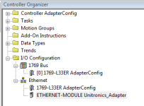
Here's a screenshot of how I think the CompactLogix I/O object should be configured:

Unitronics_Adapter_Object.png
 
Thank you for the reply Ken.

Our Controller is the Unitronics unit and the customer is integrating it with some A-B equipment.

After reading some literature last night on A-B my questions actually should have been involving configuring the MSG Instruction in the A-B unit.

The settings involving the module properties (Adapter Name, T2O, O2T, I/O Size) I think I have a decent understanding on.

My main question that comes in to play is the MSG Instruction boxes have either a Source Tag or Destination Tag. The UniStream units does not use tag addressing. The name for the Inputs or Outputs that was in previous screen capture is just a Structure (kind of like a grouping of tags) where the tags they are reading/writing is stored. I've attached another screen capture that might help you better understand the naming aspect. I've been told my Unitronics Support the naming here for them is of no importance. Is it possible to leave empty then?
 
Last edited:
Forgot attachment sorry. Also the file is .png but when uploading it is converting to .jpeg. Let me know if this one isn't any better.

MSG_Instruction.jpg
 
The configuration of the I/O Assemblies in Unitronics suggests that your customer needs to use the Generic Ethernet Module object in the CompactLogix I/O tree to establish a cyclic data exchange. This will make the Unitronics appear like an I/O module to the CompactLogix over EtherNet/IP.

The MSG instruction functions differently; as you've seen, its principal job is to read or write data table elements or controller tags. It functions on-demand, once every time the instruction is triggered, not cyclically.

The MSG instruction could also read and write the Assembly Object that's being defined in the Unitronics, but that's not how the technology is designed to work and it may not function correctly because it doesn't establish a cyclic I/O connection.

Your CompactLogix programmer could try to use the Get Attribute Single command code to read the Output Assembly and the Set Attribute Single command code to write the Input Assembly objects.

But again, the proper way is to use the I/O tree in Studio 5000 to create a cyclic I/O connection.

MSG_Assy101.jpg
 
Ken:

I may be not completely understanding you but are you saying to set it up in a cyclic connection it can be done via the configuration method of your first post?

This cyclic method you mention is how Unitronics is set up when used as a Scanner as you adjust the RPI (Requested Packet Interval) but is essentially good to go at Power Up for operations.
 
You've got the right idea. Inserting a "Generic Ethernet Module" object in the Studio 5000 I/O tree creates a cyclic I/O connection over EtherNet/IP.

That Generic Ethernet Module object is the one with the configurable Assembly numbers, datatype, and data sizes.

On the Connection tab of the configuration applet is where you set up the Requested Packet Interval.

Unitronics_Adapter_IOTree.png
 

Similar Topics

Hey guys, On my system, i got prop valve controling cylinder on the left and right to adjust the center of a lumber before it get in a woodmill...
Replies
8
Views
932
Hello, I have a machine I am programming and it seems I am unable to create a string tag for some odd reason in the pv800. CCW v 20 and pv800 fw...
Replies
3
Views
1,709
I need a little help figuring out how to fix a fault in a customer's CompactLogix. The guy said the fault happened when he was jogging the...
Replies
27
Views
5,312
Hello All, I'm stuck and have contacted AB, and still no help. I have recently upgraded 2 of 4 L32E V16 controllers to L33ER V31.011 and...
Replies
5
Views
2,222
I am trying to read a block of data from an ML-1400. The data is in the form of floating-point numbers. I am only able to read only 59 numbers...
Replies
2
Views
1,202
Back
Top Bottom