CONTROL OF 3 SERVOMOTORS KINETIX TO FILL AREA

KarajoSoft

Member
Join Date
Jan 2021
Location
washington
Posts
21
Dear colleagues,

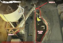
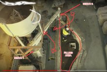
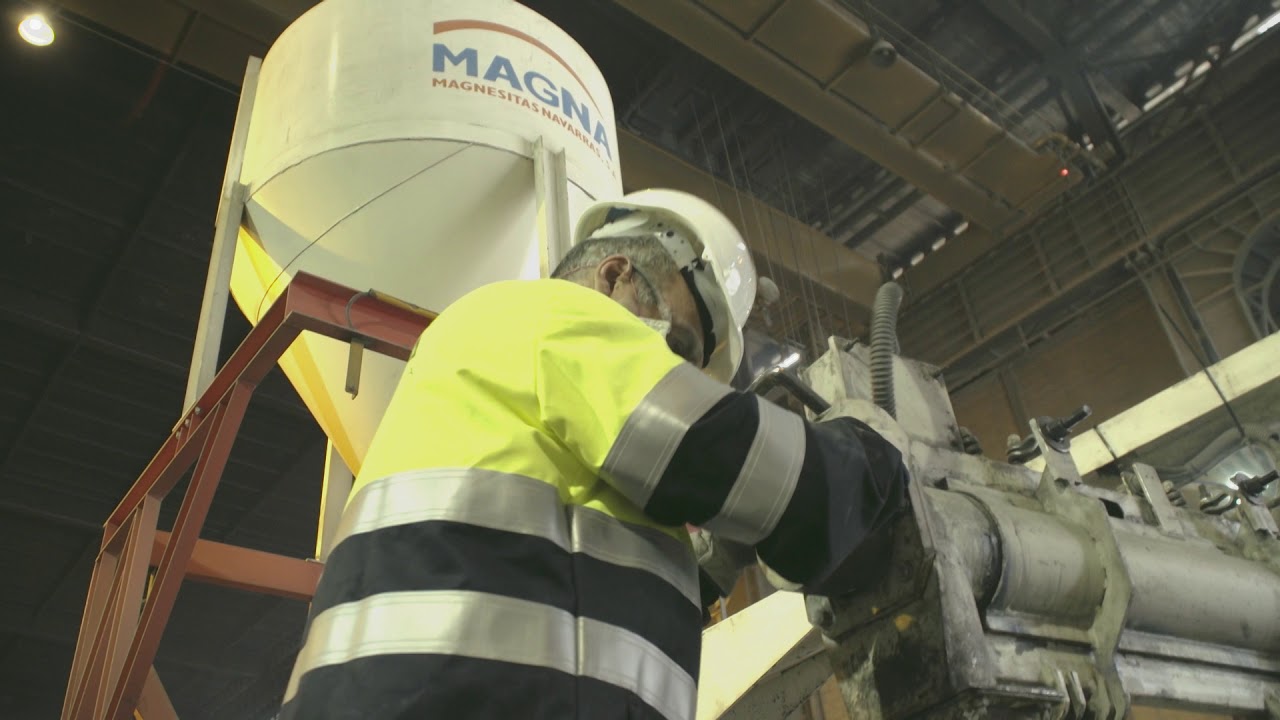
hope you can help on that matter. We have a project where we need to control 3 servomotors to move a auger feeder system (feeding is constant) to fill one area.

the tricky point here, is how to consider the program to be able to move these 3 servomotors synchronously and make the auger move throughout the area until the hopper is completely filled with product. How can do it?

I think there is some kind of library to control robot of 6 axis using kinetix 5700, but maybe there is better ideas here from some experienced colleague. To detect all the area is filled will install some kind of sensor or artificial vision.

Please find image attached for better understanding.

any suggestions are most welcome.

many many thanks!
 
Welcome to the PLCTalk forum community !

Are you the machinery OEM, or the end user building a system for your own use ? Do you have experience with simpler single-axis servo motion programming in Rockwell Automation systems, or in any other platform ?

Do you have experience with robot geometry ? The first question is "are the axes at 90 degrees to one another" (aka "orthagonal"), or is it a more complex mechanism ? Is it a sort of gantry ?

When I think about something to control a feed chute's location I generally think of a 2-axis H-gantry, but maybe you've got a pivot and chute system.

Your image didn't show up in the post; give it another shot at embedding or attaching it.

Is the motion you want generally circular, or spiral, or back-and forth "raster fill" sort of motion ?

Will there be any operator interface with the material handling system to figure out where it is most appropriate to start it, such as with a partially-full or unevenly-filled hopper ?

ControlLogix isn't a robot controller, not really. But it does simple axis coordination pretty well with the Motion Coordinate System feature.

Start with the Kinetix Motion Coordinate System User Manual.

 
I went back and checked your only other post, from 2021. It was asking about using Micro 800 controllers, Kinetix 5100 single-axis drives, an ABB SCARA Robot, and a vision system. Is this the same system ? Your mention of the Kinetix 5700 made me assume, maybe incorrectly, that you have a ControlLogix or CompactLogix that supports Kinetix motion, including coordinated motion.

Micro 800 is a much smaller, less-capable control system, and is almost certainly inappropriate for the control of a SCARA robot. Do you have a robot that's been stripped of its motors and controller ?
 
Maybe the third servomotor is the auger speed?

If I had to do this I might implement the roomba algorithm: move in a random pattern. Over time it would probably work pretty well. Maybe add a wand (analogous to this; see also here) or other distance sensor to the exit chute which slows or stops the auger when the chute is over a high spot.
 
Welcome to the PLCTalk forum community !

Are you the machinery OEM, or the end user building a system for your own use ? Do you have experience with simpler single-axis servo motion programming in Rockwell Automation systems, or in any other platform ?

Do you have experience with robot geometry ? The first question is "are the axes at 90 degrees to one another" (aka "orthagonal"), or is it a more complex mechanism ? Is it a sort of gantry ?

When I think about something to control a feed chute's location I generally think of a 2-axis H-gantry, but maybe you've got a pivot and chute system.

Your image didn't show up in the post; give it another shot at embedding or attaching it.

Is the motion you want generally circular, or spiral, or back-and forth "raster fill" sort of motion ?

Will there be any operator interface with the material handling system to figure out where it is most appropriate to start it, such as with a partially-full or unevenly-filled hopper ?

ControlLogix isn't a robot controller, not really. But it does simple axis coordination pretty well with the Motion Coordinate System feature.

Start with the Kinetix Motion Coordinate System User Manual.

Hi Ken,

many thanks for your prompt response. I'm automation engineer providing software service to OEM.

Well sorry for my short explaination im going deeper. The 3 auger fillers they are controled by 3 inverters to move its speed (that's ok). then in each join will be a servomotor to be able to move rotationally (0-360º) each auger filler to be able to reach each point of filling area, so the movements are only in X axis. the question is how considerer the programation to move sincronizaly thi 3 servomotors to make sure fill all that area.. all this must be automatic without any operator so the motion system must move to initial position and start to fill all the area. Once all area is filled return to home o or maintenance position.

I'm looking for for some system of programation to be able to do that. I'm familiar with kinetix but to move servomotors in packaging machines. with that programation i would like to get like some kind of robot arm (but only in one axis) to be able to reach all the filling area.

hope that makes clear.

thank you so much,
 

Attachments

  • LAYOUTCOLDMAG.jpg
    LAYOUTCOLDMAG.jpg
    172.9 KB · Views: 17
Maybe the third servomotor is the auger speed?

If I had to do this I might implement the roomba algorithm: move in a random pattern. Over time it would probably work pretty well. Maybe add a wand (analogous to this; see also here) or other distance sensor to the exit chute which slows or stops the auger when the chute is over a high spot.
Hi drbitboy,

can you explain how to do roomba algorithm with rockwell and kinetix? This system sound good for me since we need to move this 3 servmotors in X dimention to reach each courner of the filling area. So all this 3 servomotors move 0-360 of the arms (the auger fillers) to reach filling area. Any idea how to start with the programation? About to get the maximum filling for me is not problem, we can add sensor to know when we reach the top to start to move to another position .

thank you,
 

Attachments

  • LAYOUTCOLDMAG.jpg
    LAYOUTCOLDMAG.jpg
    172.9 KB · Views: 11
Hi drbitboy,

can you explain how to do roomba algorithm with rockwell and kinetix? This system sound good for me since we need to move this 3 servmotors in X dimention to reach each courner of the filling area. So all this 3 servomotors move 0-360 of the arms (the auger fillers) to reach filling area. Any idea how to start with the programation? About to get the maximum filling for me is not problem, we can add sensor to know when we reach the top to start to move to another position .

thank you,
Ah, so there are two servomotors controlling the two angles? You mention a third servomotor but I don't see it in that image.

And the two arms have fixed lengths?

So the position of the filler is
  • X = ArmLength1 * cosine(servoangle1) + ArmLength2 * cosine(servoangle1+servoangle2)
  • Y = ArmLength1 * sine(servoangle1) + ArmLength2 * sine(servoangle1+servoangle2)
where servoangle1 is the angle, counter-clockwise from "down" in the image, of the long arm, and servoangle2 is the angle, counter clockwise from parallel to the long arm, of the short arm?

So in the picture, if I estimate by eye, servoangle1 would be about 150°, and servoangle2 would be about 240° (or -120°)?
Hi ,

Two arms and the future 3 arms (arm=auger filler) have fixed lenght and only move rotationaly (0-.360º )
servo 1-_>move rotationaly left to the right) big auger filler
Servo 2-->Move rotationaly left to the right medium auger filler (dosn't appear in the picture)
Servo 3-->Move rotationaly left to the right small auger filler (where the product drops into recipient)

Thank you foe your replay. I've appreciate a lot. Will be probably 3 servotomotoe this servomotor only moves this 3 auger fillers horrizontally/rotationaly( x dimension to 0-360° depending of mechanical design). By moving this 3 servomotor sincronized must reach each point of the filling area to fill qith product until top. So I need some kind of movement to pass trough all this area filling this recipient.

Thank you so much
 

Attachments

  • LAYOUTCOLDMAG.jpg
    LAYOUTCOLDMAG.jpg
    183.6 KB · Views: 8
Last edited:
The roomba algorithm is very simple:
  1. it picks a random direction and moves in that direction
  2. if it hits something, go to step 1.
in this case, there would need to be a model for the walls (or the center of the delivery chute when it is at the wall), so that "hit something" can be evaluated, and a model of servomotor angles and arms to calculate the position of the delivery chute and to move the delivery chute in a straight line.

A straight line is not necessary, and it could simply pick two random angular speeds that combine to move away from the wall, one for each motor, and the delivery chute would follow a series of curved lines.
 
Hi,

But I cannot crash with auger filler against the walla. I need to fill all that recipient while moving above it. So I need to create some kind of movement mapping.

I was thinking to use coordinat motion functions like MCLM. Seem quite good to create a cartasian movement XY but what if finally I get third servomotor?

Any more suggestions will help.

Thank you,
 
Thanks for the photo. Can you explain what the end process is ?

This looks the most like a "SCARA Independent" coordinate system. There aren't any linear actuators, just two rotary ones. Rockwell ControlLogix/CompactLogix includes SCARA independent kinematics in the ordinary coordinated motion system option selections.

You should define how you think about the fill area as a cartesian coordinate system. Then the robot kinematics has to convert J1 and J2 angles, knowing fixed L1 and L2 link lengths, to get X and Y positions.

How you choose to program this for the fill algorithm or pattern is something you should talk to the customer about. A perimeter path, or a raster fill traveling along the longest sides seems the most sensible for that work envelope. Maybe even a set of fanned arcs.

Are there inserts or voids or other areas of the fill area that don't get filled, depending on what's being produced ?

Coordinate System.png
 
Thanks for the photo. Can you explain what the end process is ?

This looks the most like a "SCARA Independent" coordinate system. There aren't any linear actuators, just two rotary ones. Rockwell ControlLogix/CompactLogix includes SCARA independent kinematics in the ordinary coordinated motion system option selections.

You should define how you think about the fill area as a cartesian coordinate system. Then the robot kinematics has to convert J1 and J2 angles, knowing fixed L1 and L2 link lengths, to get X and Y positions.

How you choose to program this for the fill algorithm or pattern is something you should talk to the customer about. A perimeter path, or a raster fill traveling along the longest sides seems the most sensible for that work envelope. Maybe even a set of fanned arcs.

Are there inserts or voids or other areas of the fill area that don't get filled, depending on what's being produced ?

View attachment 68968
Hi Ken,

thank you so much for your super useful help. I've really appreaciate it. the end proces is to make a automatic sistem to fill "FILLING AREA" to get like a second wall with refractory material to coat the "container" for foundry industry:Watch the video.


so we would have probabibly 3 auger filler and we need to move them (0-360º) coordinated to reach to fill all that container. My question is can a coordinated scara o MCLV coordinated motion system to add 3 servos and considerer only two dimentions ( XY) ?

As there is not linear movement, each servo has XY dimention movements right? How can manage that to coordinated all of them and get like XY general position?

The idea should be something to put the "positions" on HMI and the system follow them, or even better like make "teach" positions and saved as good positions to move from one to other.

I'm not experiencied with this kind of coordinated motion, but yes with virtual axis and several other servo for example for HFFS machinery.

thank you again for your help!
 
Last edited:
Hi Ken,

thank you so much for your super useful help. I've really appreaciate it. the end proces is to make a automatic sistem to fill "FILLING AREA" to get like a second wall with refractory material to coat the "container" for foundry industry:Watch the video.


so we would have probabibly 3 auger filler and we need to move them (0-360º) coordinated to reach to fill all that container. My question is can a coordinated scara o MCLV coordinated motion system to add 3 servos and considerer only two dimentions ( XY) ?

As there is not linear movement, each servo has XY dimention movements right? How can manage that to coordinated all of them and get like XY general position?

The idea should be something to put the "positions" on HMI and the system follow them, or even better like make "teach" positions and saved as good positions to move from one to other.

I'm not experiencied with this kind of coordinated motion, but yes with virtual axis and several other servo for example for HFFS machinery.

thank you again for your help!
I need this kind of configuration: A Scara independent with 3 arms (3 links). Is it possible?

thanks!

1711211034594.png
 
Brian explained the basic math to get an X/Y Cartesian position from the angles and the link lengths above:
  • X = ArmLength1 * cosine(servoangle1) + ArmLength2 * cosine(servoangle1+servoangle2)
  • Y = ArmLength1 * sine(servoangle1) + ArmLength2 * sine(servoangle1+servoangle2)
The benefit of having a multi-axis coordinated motion system in the ControlLogix is that it handles not just that position transformation but also the planning of a move in X-Y space. You can appreciate that with this kind of mechanism, moving the tool endpoint in a straight line involves coordination between the linked rotary actuators.

In your application, it looks like there will be a handful of tundish shapes, so you might have a recipe or program handling system that is much simpler than a general-purpose CNC tool would use. Teaching the machine by manual manipulation and the pushbutton designation of teach points might even be a workable method of creating a sequence of moves.

If operators will be in close proximity to this motorized system, obviously a risk analysis is necessary. And foundries are dirty on their best days, so motors, mechanisms, and operator interface will all need to be pretty rugged.

I am not sure how to configure Studio 5000 to work with a third link. My understanding is that traditionally for a "SCARA Independent" robot there are 2 links and a rotary axis at the end, and/or a vertical Z-axis at the end of the arm.

There are certainly some Forum members with more experience in robot kinematics and Logix 5000 than I have.
Hi,

yes i saw his calculations and are similar to one specialized guy that i find and i will in contact with him on monday. This is pure maths, we need maths to get XY position and

1711230084312.png

maths to get the position of servos in º:

1711230161540.png

doing maths and writing Structured text I guess to be able to manage all that system of 2 o 3 servos depending of machine. It is not pre-defined movement from Rockwell. Hopefully some good motion guy come to this post to add his experience and get more knowledge.

I've appreciate your help mates :)
 

Similar Topics

I’m attempt to establish a communication between two simulator M580 CPUs, using a READ_VAR, I have two vitalization Windows 10 in VMWare and each...
Replies
0
Views
22
Adding ethernet equipment to an existing panel that has none. We have some solid ethernet cables coming from other remote cabinets that I plan to...
Replies
3
Views
124
does anyone have an install or know if/where i can download it for the following "ABB PS501 Control Builder Plus V2.3 " the software was a free...
Replies
2
Views
89
I am not sure why this is requested, but it was asked. Currently I have one PLC , with one output to a relay, turning on a field equipment (just...
Replies
7
Views
217
I have been requested to test this proportioning valve for PLC control of flow/pressure. Dwyer Series SVP Proportioning Solenoid Valve The flow...
Replies
10
Views
421
Back
Top Bottom