ControlLogix 1756-IF16 Input Scaling

jjimen03

Member
Join Date
Aug 2016
Location
New York
Posts
12
Hello folks,

If I am using the 1756-IF16 Analog Input card to sense a 0 - 20mA input signal, in RSLogix 500, under the Module Properties -> High Signal Scaling, why can't I change the High Signal from 20.0 mA to say, 20.5 mA?

When I try to do so, I get an error stating that the
"Signal Settings Must Be Within Range"

The reason is that I am getting Out of Range Alarms when the field device is outputting say, 20.2 mA into the Analog Card, so I want to respan the card's input mA signal and Engineering Ranges.

Thoughts?
Thanks in advance
 
There are only four signal types your module will accept, three voltage(-10 to 10 VDC, 0 to 5 VDC and 0 to 10 VDC) and one current (0-20 mA).

You cannot "tweak" these signal ranges; they are hardware dependent.

You could (if configurable) calibrate your sensor as to output 20 mA when the physical variable is at its maximum value (and 0 mA when at the minimum value) or use your own engineering values when processing the signals (High Engineering, Low Engineering).

If your sensor signals 20.2 mA at maximum physical variable value and 0.2 mA at minimum then you would scale your module as:

High Signal = 20.0 mA High Engineering = 20.2

Low Signal = 0.0 mA Low Engineering = 0.2

Again, for accuracy and linearity purposes, one would try to calibrate the sensor first, ensuring the proper functionality, before trying to "make" the signal look as it should.
 
Hello folks,

If I am using the 1756-IF16 Analog Input card to sense a 0 - 20mA input signal, in RSLogix 500, under the Module Properties -> High Signal Scaling, why can't I change the High Signal from 20.0 mA to say, 20.5 mA?

When I try to do so, I get an error stating that the
"Signal Settings Must Be Within Range"

The reason is that I am getting Out of Range Alarms when the field device is outputting say, 20.2 mA into the Analog Card, so I want to respan the card's input mA signal and Engineering Ranges.

Thoughts?
Thanks in advance

Just accept that the card "range" is 0-20mA, it's an industry standard, although most current loop transmitters are 4.0 to 20.0 mA

If yours is, then set Min Signal to 4.0 mA and Max signal to 20.0 mA - set your Engineering Units Min and Max as required.

If the process measurement is outside the EU range, then the input would be below 4mA, or above 20mA. The module will continue to give a "scaled" reading extended beyond the programmed range - how much depends on the model of the module - but will indicate Under or Overrange in the I tag.
 
My two cents: forget about using the hardware level out of range alarms. Disable them in the card configuration, and make your own at the software level.

Have a read of this recent thread and you'll probably get a feel for why :)
 
..... Disable them in the card configuration, and make your own at the software level.

You can't "disable them", they will always be present in the I tag, you just don't need to use them in your code.

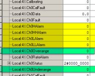
The channel "Overrange" and "Underrange" bits will indicate that the input to the module is above and below the Scaling configuration of "High Signal" and "Low Signal" respectively.

The module also has 4 "Process Alarms", High-High, High, Low, & Low-Low, that can be configured outside of the Scaling configuration of the "High Engineering" and "Low Engineering" values. You could use these process alarms instead of writing code to signal "out-of-range" by some extended margin.

2017-04-06_094113.jpg
 
NB. The Process Alarms mentioned above are only available on the IF16 when the module is configured for "Float Data - Differential Mode", meaning you only get 8-channels, or "High-Speed" mode, meaning you only get 4 channels.

If you choose "Single-Ended" mode, you can only get the process alarms for the 16 channels with "Integer Data - Single-Ended" mode.
 
You've piqued my interest...

On all of my commissioning jobs, I disable the alarms for any unused analog channels. Most of my panels use 1734 Point I/O, and if you have an out of range input on a 1734-IExC then it's channel indicator lights up red. Which upsets my OCD, and causes misdirection for the sometimes inexperienced technicians trying to troubleshoot something later on. So, any unused channels get the "disable alarms" treatment at the hardware level.

However, I've just gone for a closer look at one of my programs. This one has a local 1769 rack, including a 1769-IF16C that the OP is using, as well as several remote 1734 racks with 1734-IE8C's.

In the hardware configuration for the 1769-IF16C, there is a checkbox labelled "Disable Process Alarms", as well as one labelled "Latch Process Alarms". This can be individually configured for each channel. If checked on a particular channel, this would presumably leave the Overrange/Underrange bits active. Although I've never bothered to go looking in the input structure to see if this is the case, and since the IF16C only has a single "OK" led, which is not affected by out of range inputs, I have no red lights to trigger my OCD and I am none the wiser.

In the hardware configuration for the 1734-IE8C, on the other hand, the two checkboxes for each channel are labelled "Disable All Alarms" and "Latch Process Alarms". So, I now wonder if perhaps checking the first box on a certain channel of a 1734 analog input card would in fact stop the Overrange and Underrange members of the input data coming on, or whether it just stops the red light coming on?

Next time I'm on one of these jobs, I'm going to have to check this out...my curiosity has been stirred!

I may be wrong, but I believe you will find that the Over/Under Range status bits are not classed with the Process Alarms - disabling Alarms I don't think suppresses the out-of-range status bits.

Of course this may be different for different modules, maybe different between firmwares for the same module.... all depending on who got the job of writing the firmware, and whether he's having a bad day, or his coffee was cold.
 
I may be wrong, but I believe you will find that the Over/Under Range status bits are not classed with the Process Alarms - disabling Alarms I don't think suppresses the out-of-range status bits.
I'd hazard the same guess - but when one card specifies "Disable PROCESS Alarms" and "Latch "PROCESS" Alarms, and then the other specifies "Disable ALL Alarms" and "Latch PROCESS Alarms", I wonder if, on the latter card, the over/under range bits are included in the "Disable ALL Alarms" bit? I'm going to have to check...

Of course this may be different for different modules, maybe different between firmwares for the same module.... all depending on who got the job of writing the firmware, and whether he's having a bad day, or his coffee was cold.
Ain't that the truth :D
 

Similar Topics

Hi , hope everyone is doing well, 1756-IF16 Single-ended mode ,Input range; ±10V 0…10V 0…5V 0…20 mA Can it be used for 4-20mA or do I need to...
Replies
5
Views
3,390
Is there a way to see what the actual field signal value is going into each channel of the Analog Input I/O card 1756-IF16? In other words, I...
Replies
4
Views
3,660
Hi all, I set 1756-IF16 Analog input card's input range to 0 ~ 20 mA. 20 mA is equal to 20000 Engineering unit. Is it possible to get input more...
Replies
3
Views
5,175
We have a project where we have the 1756-L82Es in redundancy with Remote IO Backplant via EN2TRs. Everything works and is redundant but we can...
Replies
2
Views
369
Hi there! I posted few days ago about a fault i had with my motion. I did some cable check and replacement and it didnt solve my problem yet but...
Replies
0
Views
371
Back
Top Bottom