Engineering Units

Meyers Mills

Member
Join Date
Dec 2019
Location
Accra
Posts
37
Hi
I am newbie, I want to know the formula for converting raw counts to Engineering .Lets assume that the a temperature range of 0-100 degrees , you need to scale the signal from your source. Siemens uses 15 bit with range of 0-32000.Your analog signal is 4-20 mA and converted to bits .How do you scale it meaningful engineering units like degree Celsius
 
This is probably not what you want to hear, but Siemens has functions to scale the analog inputs...

Bonus, the help section for these functions also lists the formula used.
 
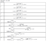
Attached is a PIC of a function block I did some years ago, the only thing is on some PLC platforms a Divide on zero in segment 8 could cause a divide by zero error if the parameters were incorrect. but if correctly parameterised will not cause problems Note: this was written as a function block so the parameters are passed to the function In_max to Out_Min and Lin_Scale is the converted output an example is:
IN_MAX : 32000 Analog in maximum
IN_MIN : 0 Analog in Min
OUT_MAX : 1500 Scaled out Max
OUT_MIN : 0 Scaled out Min
VAR_IN : this is the analogue input to scale
LIN_SCALE : This is the scaled output
The inputs are converted to reals so maths give a true representation of the scale, the output is converted back to an integer so at max it would be 1500 or (150.0) this could be left as a real number, bit just happened that the HMI only handled integers with applied decimal points.
Again you could have the scaled Min & Max as reals
There is a simple PI block as well, this was a simple block to control a motor or propotioning valve that worked well (did not need the Derivitive). For some reason it did not attach the file see 2 posts on
 
Last edited:
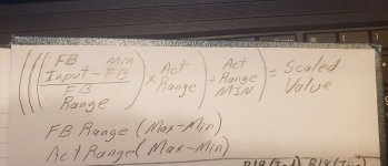
The formula is as follows:
Rate = (scaled max. - scaled min.) / (input max. - input min.)
Offset = scaled minimum - (input minimum x rate)
Scaled value = (input value x rate) + offset

Input value-0-32000 from sensor
Input Min-0 minimum reading from sensor
Input Max-32000 maximum reading from sensor
Scaled Min-0 minimum (C)
Scaled Max-100 maximum (C)
Scaled Value-actual degrees (C)

This will just give you a ballpark scaled value. If you need the actual temperature you have to calibrate it at both ends of the scale.

Calibration
0 degrees (C)---Fill a cup with ice and water give it a few min to equilibrate, put the temp probe in the middle of the ice bath and copy the Input Value from sensor to the Input Min value of equation.

100 degrees (C)---Put the temp probe in either a known temperature equilibration block set at 100 degrees or boiling water, then copy the Input Value from sensor reading to the Input Max value of the equation.

In the real world we would choose a high quality Thermocouple or RTD that is rated for the temperature range needed and then also calibrate it at least once to verify values.

There are also some thermocouple type cards available that will do most of this for you as long as you know what kind of thermocouple you are using.
 
Oops for some reason it did not appear I was going to add the formula but it's already been added while I was uploading this doh...

Scaler.png
 
Last edited:
Y = MX + B

learn the ins and outs of the above equation and you can scale any hi/low to another hi/low (linear scaling).
 
Jsu 0234M, your formulae is quite straight forward. Does it for all analog quantities like pressure, weight, temperature, strain etc?
What is the margin of error if any
 
The scaling shown would change the raw input into whatever output range you enter.

It could be temperature, pressure, flow, distance, velocity, weight, pH, conductivity, or anything being sent by analog signal.

As far as the margin of error the calculation would not enter any error into the output if properly done, but there might be a slight error in the PLC reading the input value (say 4.06mA vs 4.07mA where the actual input process hasn't changed) But that would effect the raw input no matter what was done with it.
 
Jsu 0234M, your formulae is quite straight forward. Does it for all analog quantities like pressure, weight, temperature, strain etc?
What is the margin of error if any


Aabeck is right, the formula will work for anything as long as you have good data coming in and you know how to properly calibrate it for what you need out.
 
I use this formula extensively. The PLC I use can scale the analog signals for you, but I STILL prefer those raw values (4000-20000, 0-65536, etc.) scaled to standard signals with my own math. The scaled values can be changed through the HMI instead of being permanently stored in the configuration file, requiring a change with a pc. I use this math to create curve characterizers/function generators as well. I use one set of math instructions, and use select blocks on the x breakpoints to choose which min/max values to input into the math. Works great. Here is another way to express it:

scaled value = (((a-b)/(c-b))*((e-d)+d))+f
where:
a=raw value
b=raw minimum
c=raw maximum
d=EU minimum
e=EU maximum
f=EU bias/shift (optional, handy for calibration at a specific point)
 
Last edited:
Jsu 0234M, your formulae is quite straight forward. Does it for all analog quantities like pressure, weight, temperature, strain etc?
What is the margin of error if any


This is an interesting question.


The margin of error is wholly dependent on how linear the [transducer+A/D] system is in converting the physical phenomenon into raw counts, so there is no single answer. For many measurements (pressure, weight, strain), it is "close enough," or if not, it may be close enough over a limited range (e.g. thermocouples, but they are usually handled differently because of the known characteristics of the various metals involved).


Most measurement vendors quote an accuracy in their literature, but to definitively answer that question, you need to do a proper calibration on every system at several points over your range of interest.


Now all of that is indeed interesting, but my real question is, why would someone who seems to have responsibility for a measurement system be asking this question in the first place? Did they even understand what I meant by "linear" above?


I am not trying to demean the OP or their educational background, but one of the fundamental concepts of engineering is proportions, and anyone who understands proportions would not be asking the original question. And although you will get an answer here (the many versions of the formula posted in response), I am concerned about the difference between having a formula and understanding a formula.


With that in view, would the OP mind providing the context for their question?
 
I think I learned more algebra while programming than I did in high school. I still don't know s***. It takes a formula to know a formula.

OP: The floating point math on the software side of things is essentially error free in most linear applications. Errors in your physical hardware... sensors, wiring, input cards... is a whole 'nother story.
 
Last edited:
I really appreciate your inputs to my post, thanks for your support! I can now program most PLC brands.
Next is SCADA.This is the best automation blog on the planet

Facebook /wise Samlafo
 
Last edited:

Similar Topics

Just curious - I see there are channel configurations for the 5069-IF modules that let me type in the high & low Engineering units as well as the...
Replies
3
Views
1,002
Hi, Our PLC measures WATER FLOW RATE as an analog input. The PLC reads it as an integer value (D34) in the range 0-4000 as follows: Range...
Replies
12
Views
2,570
Context: Mitsubishi Q series Hi, today I configured an analogue input into the PLC. Then I injected 4-20mA at the terminal block. The digital...
Replies
47
Views
11,525
I need to scale a raw value into Engineering units. i don't think there is a standard scaling block in PLC 5 instruction set (or i didn't see...
Replies
19
Views
7,278
Hi All, Just have a quick question would appreciate your advice, I am using a 1734-IE2V AB card on a point IO and connecting a small pressure...
Replies
3
Views
2,327
Back
Top Bottom