First Out Alarming

Thanks Guys

I have attached code I got from another thread on here, which looks to be doing the same thing, an OR and then a NEQ.
Again I would just like to see it as bits now as oppose to words. In this example it mentions alarm state(b219) = 0, so B219=1 is good, im not sure what B220 initial state should be?

Lets say it is also a 1, then as soon as we get an alarm (b219 = 0) then B220 would stay a 1 (0 or 1 = 1) and nothing would change.
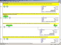
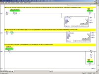
1.jpg 2.jpg
 
What i am thinking is happening is that FIRST_OUT_SD_IN gets set to 1 on a scan of the PLC and then on the second scan the OR instruction gets executed?
 
What i am thinking is happening is that FIRST_OUT_SD_IN gets set to 1 on a scan of the PLC and then on the second scan the OR instruction gets executed?
No, I guess they got it right after all. In your program, as long as the alarm input word FIRST_OUT_SD_IN has not changed since the last scan, (this is equivalent to saying A OR A = A) then the OR destination FIRST_OUT_SD_ON will be equal to FIRST_OUT_SD_IN. Therefore, Rung 6 will not do anything. However, on Rung 5, if FIRST_OUT_SD_IN changes by 1 bit, then the OR Destination (A OR B) is suddenly NOT EQUAL to A, so on Rung 6, then FIRST_OUT_SD_IN is indeed NOT EQUAL to FIRST_OUT_SD_ON.

Think of it like this: On each scan, when the new A = old A = B, then the OR moves (A OR A) to Destination. But when an alarm occurs (by definition, new A is different from old A by 1 bit), then new A NOT EQUAL to old A, therefore the OR moves the result of (A OR B) to Destination.
 
Last edited:
I guess I should reply since this looks like the first out logic I use. Echos, I don't think it's one of my programs because I can't recall doing a first out routine that only uses 16 alarm inputs. All of mine use more alarms, hence the reason I use the FAL instruction version. This first out logic has been floating around Alberta for quite a few years and has been used in many applications. The rung comments for my programs are identical word for word to yours.

The biggest thing that you are missing is that this logic is written for an 'off-equals-alarm' situation. If you're trying to make it work with 'on' being alarm it won't work. That's the whole reason for the tag 'FIRST_OUT_SD_IN'. It's your alarm file. You need to program this so that every bit in that word will be off to alarm/shutdown. In other words, whatever is wired to input 0 in your logic should be fail safe. If it isn't wired that way and you're using one to alarm, simply change the XIC to an XIO for input 0.
 
Hi Grs

Thank you for your reply. I download my program to RSEmulate and it did not simulate that good. I just want a solid program that I can figure out how it functions.

Is it possible you could post your logic here, since it has been fully tested?
 
The logic you posted in post #16 is the logic I normally use. It's been adapted to RSLogix 5000 but the instructions are still the same. The only thing you have to do is to 'load' the B219 file. If you type in the following it's an example of the type of 'loading' I'm talking about:

SOR XIC I:000/00 OTE B219:0/0 EOR SOR XIC I:000/01 OTE B219:0/1 EOR SOR XIC I:000/02 OTE B219:0/2

For RSLogix 5000, B219:0 is the equivalent of the tag FIRST_OUT_SD_IN and I:000/xx would be the alarms. As many alarms as you want to determine the first out on is how many rungs you'll need. As I mentioned previously, the B219 file has to be zero to alarm otherwise it won't work. So some of the XIC's above may have to be XIO's, depending on how your program is configured.
 
+1 for post 16 when there are more than a big handful of alarm words mapped as bit alarms. If they are alarm codes, I prefer to use many NEQ instructions to reveal individual mismatches at a glance in ladder until I get to more than a dozen or so words, then I switch to the FAL.

Notice that alarm file is 206 in length? I bet many of those addresses are word alarm codes...maybe not...I have a machine that is "over-alarmed", it probably has over a hundred INTs worth of bit alarms.

You can do the FAL with lesser instructions to get the same effect with different platforms,, I tend to use the NEQ to trigger it all, even 6 or 10 of them in parallel to drive a "New Alarm" bit which FIFOs using a downward COPy instruction group to move the copy of the new bit pattern and a timestamp if needed into the circular alarm queue, along with the XOR's list of mismatched bits for that index position.
 
Last edited:

Similar Topics

Is there any benefit to using ALMD instructions in a Studio 5000 project when the HMI is using FTView ME? We are currently triggering our alarms...
Replies
2
Views
3,433
Hi there, I've spent over a day now struggling with setting up an alarm and event server for FTView10. Poor documentation tells me they have...
Replies
3
Views
2,017
So I'm looking at putting in a cellular alarm. I'll have about 4-6 alarms, and I would like to send out text messages to a list of phone numbers...
Replies
16
Views
4,182
Anyone else playing with this today? Just got it to work right now with FTV SE.
Replies
4
Views
1,961
Hi, Not specific to any manufacturer of PLC or HMI/Scada but looking for best approach. To ensure a HMI/Scada receives the alarm I assume most...
Replies
3
Views
1,249
Back
Top Bottom