Hi, i am trying to use a different method of using one pushbutton to start/stop a system. I know how to do it using two rungs and a one shot. I seen logic on here using a one shot rising with and XOR command. I cannot get it to work with logix 5000. I guess i am not familiar with the XOR command tells me invalid argument. And the one shot looks for a storage bit....just looking for some guidance. Anyone help me out. thanks,
You are using an out of date browser. It may not display this or other websites correctly.
You should upgrade or use an alternative browser.
You should upgrade or use an alternative browser.
Flip Flop Logic
- Thread starter icehube
- Start date
Hello,
in RSLogix 5000, the XOR instruction works with SINT, INT or DINT data, not with booleans. For booleans you have to use the BXOR instruction wich just exists for "function Block" and "structures text".
But ladder XOR instruction is just:
in RSLogix 5000, the XOR instruction works with SINT, INT or DINT data, not with booleans. For booleans you have to use the BXOR instruction wich just exists for "function Block" and "structures text".
But ladder XOR instruction is just:
     a       b

----| |-----|/|---------

I    a       b     I

----|/|-----| |-----
Last edited:
Short Circuit
Member
How does it work with a real input wich come back at 1 in the next PLC scan ?
My own way. not so elegant but work with all types of PLC.
My own way. not so elegant but work with all types of PLC.
    I        b2       O        b1

---| |---=--|/|------|/|------( )---

         |        |        |   O

         |        |        ---(L)---

         |        |   b1       O

         |        ---|/|------(U)---

         |                     b2

         ---------------------( )---
Last edited:
dcooper33
Lifetime Supporting Member + Moderator
Ice,
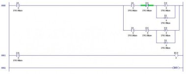
I have this one-button, one-rung flip flop ladder that might work for you. Everytime the Input I:0.0 goes from OFF to ON the Output O:0.0 toggles.
The second rung (0001) is for test purposes only, to prove that the logic works, it can be deleted.
I'm sorry but I don't see how that code is going to work. Unless you are able to hit that input button for one scan only, then the output is going to toggle states every scan as long as I:0/0 is high.
It's also poor programming practice to try to change the state of an input through logic. While in theory this does change the state of the input in the logic for the duration of the logic scan, this state will be overwritten by the real world input at the beginning of the next scan anyway.
Search the forum for flip flop. You can read for days.
My favorite method (due to simplicity) is using a counter accumulator LSB to control the output toggling. There are more efficient methods, and more universally applicable, but in most cases, PLC memory is cheap, but troubleshooting time is not!
We should have a contest on the forum to see who can write the most obscure, most inefficient, and most indirect method of flip-flop logic that functions correctly. That would be an interesting thread! :nodi:
Ian, you got that right. I added Jean-Luc's method to the collection, making 12 tested working methods for the Allen Bradley PLCs, and some methods will work for almost any PLC. See the attached PDF file. The ZIP file is the original LogixPro simulator version.This has been answered many times over by all of us over more than 12 years.
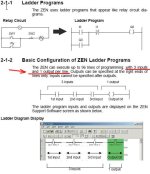
Jean-Luc, there are some PLCs that only allow one output per rung (Omron ZEN for example). For those, you would need Method 5, 8, or 9.
I see that Icehube's scheme is the old 2-rung Method #7 in the PDF file. When you tried to use Method 11, with a XOR, notice that the bit that the XOR will turn on/off is the same bit number in the Output Word as used in the OTE directly above. In other words, if you use address B3:2/10 in the OTE, and B3:2 as the XOR Source, then the XOR will change only bit 10 of whatever Output word you use in the Source B and Destination (which should be the same word).
Last edited:
Eric Nelson
Lifetime Supporting Member + Moderator
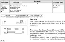
Yes, the ZEN does have an ALT function (short for Alternator), and it does work well to alternate an output between on and off. At least the Japanese designers knew enough English grammar and diction not to name it a flip-flop (child's sandal, and also an electronic bistable multivibrator chip).I think the ZEN has an 'ALT' function which is the FlipFlop
The ZEN also has severe limitations for its ladder rungs. Only one output is allowed, and only 1 rung branch on the left (input) side can be used. It really needs the ALT function.

Last edited:
Similar Topics
I am having this issue trying to figure out how to do this. I have a Hydraulic ram that travels when a machine is running. The ram extends to the...
- Replies
- 31
- Views
- 9,562
U
how can i create a flip flop in ladder logic? It needs to be triggered by one input and has two out puts that flip flop with no time limit for...
- Unregistered
- LIVE PLC Questions And Answers
- Replies
- 20
- Views
- 55,363
C
where can i see some sample logic looking for a momentary input/"maintianed on state" then the same momentary input for fot the maintained off...
- cclarsencc
- LIVE PLC Questions And Answers
- Replies
- 46
- Views
- 33,869
Hi everyone,
I'm learning ladder logic and have built a flip flop circuit (see pic) from an online tutorial. Closing the switch A is meant to...
- Replies
- 19
- Views
- 6,951
I found and fixed issue. B3:3 was used in MOV.
- Replies
- 11
- Views
- 2,609


