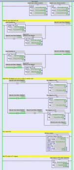
Flow PID and Level P-Only controls working together

I also have a P-only control (P = 20) providing a value from -10 to +10 that gets added to the first PID output. That value then drives the pump VFD. This works to a point but does not go far enough.


That is to be expected as it is the nature of a P-only controller: if the load (external conditions) changes, then the controller responds when that disturbance effects a change in PV (i.e. Error). That will reduce Error, but P-only cannot drive PV all the way back to SP, i.e. P-only cannot eliminate Error, until the load returns to the original state.

It's good to go back and re-read the OP.
 
I realize I can't control both at the same time - I have seen that question posted in many other threads and based on the responses I knew that was going to be the perception but that's not what I am really trying to do.

Instead of saying I needed flow to be primary and level secondary, maybe I should have said Flow was only of concern until I have to do something to bring the level back to setpoint, then a small flow change is permitted.

I don't need very tight level control, just control over spillage or emptiness.

So I had an epiphany
When the level gains or lowers by a small amount I simply adjust the flow setpoint lower or higher by a fixed amount till the level returns to setpoint. Works like a charm.
-
 
When the level gains or lowers by a small amount I simply adjust the flow setpoint lower or higher by a fixed amount till the level returns to setpoint.


What happens if the fixed-amount adjustment to the flow setpoint is not enough i.e. the adjustment is not enough to reverse the level's movement?
 

GRT LEVELpv LEVELhi ADD SPbase SPdelta SPflow ### Add delta to base flowrate setpoint when level is above deadband high limit

GRT LEVELpv LEVELlo SUB SPbase SPdelta SPflow ### Subtract delta from base flowrate setpoint when level is below deadband low limit

BST LES LEVELpv LEVELsp GRT SPflow SPbase NXB GRT LEVELpv LEVELsp LES SPflow SPbase BND MOV SPbase SPflow ### Use base flowrate setpoint when level crosses target level from either deadband limit


Where

  • SPbase = base flowrate setpoint i.e. when not in level control
  • LEVELpv = current level measurement
  • LEVELlo < LEVELsp < LEVELhi (level deadband around "soft" level setpoint)
  • SPdelta > 0 (flowrate increment or decrement wrt SPbase when in level control)
  • SPflow = Flowrate setpoint that is input to PID

i.e. basically a two-way start-stop pattern?


Caveat: it's missing explicit initialization, but will kick in the first time LEVELpv goes outside the level deadband
 
Last edited:
P.S. I finally realized what this is: two-way bang-bang control; i.e. equivalent to starting a sump pump when the sump level is high, and stopping the pump when level is low. At first glance it does not appear that way because the "quiescent" state, when level is not in control, has a non-zero pump rate, but other than that offset, that's what this is. @Waterboy's code demonstrates this.

Also, I am curious about the nature of the downstream process, which apparently requires a fixed target flowrate from the tank outlet, which flowrate may be different than the tank inlet flowrate, but at the same time that process is accepting of a short-term step change of flowrate beyond the inlet flowrate with respect to the target flowrate.
 
I suppose that's fair, though this has the equivalent of pump down and pump up states. I've not heard the term bang-bang control.

The reason to stabilize the downstream flow is chemical dosing. Allowing a small change of flow over a long time is preferred to a large change of shorter duration.

Its been running for 24 hours and I see a 34 minute repeating pattern that indicates to me that there is loss of volume between influent of the process stream and the tank due to the process. I think I have an idea where that happens so compensating for that that's todays quest.

Oscillating.jpg
 
this has the equivalent of pump down and pump up states.


That's why I said "two-way" bang-bang control. The "bang-bang" refers to on-or-off - i.e. fixed step changes to - settings for the control variable (the flowrate PID SP).


The reason to stabilize the downstream flow is chemical dosing. Allowing a small change of flow over a long time is preferred to a large change of shorter duration.


It's actually the other way round: large change over long time vs. small change of shorter duration; but with dosing I understand that duration would be the primary issue.


Its been running for 24 hours and I see a 34 minute repeating pattern that indicates to me that there is loss of volume between influent of the process stream and the tank due to the process. I think I have an idea where that happens so compensating for that that's todays quest.


Not sure what you mean by "loss of volume." What I see is that the influent flowrate is typically less than the un-tweaked base target effluent flowrate, so the level drops until the level lower deadband limit is reached, at which point the effluent flowrate (represented by PID.CV, presumably the VFD speed reference?) is tweaked (reduced) until the level recovers.


The long-term slope of the level signal could be estimated and used to calculate the mean influent flowrate, which could be used to update the base target effluent flowrate setpoint and extend the 34-minute cycle by quite a bit, but there may be too much noise in the influent flowrate and/or level measurement for that to work.
 
It's actually the other way round: large change over long time vs. small change of shorter duration
no... it's not in this case. a small change to flow over a long time is preferred to large change of flow for a short time.

Not sure what you mean by "loss of volume."
There are points where stream samples are constantly taken that are not accounted for in the effluent display. I can measure and add those and that should clean that up. Effluent Rate display wont match influent rate display, but that's OK since it's accurate .
 
no... it's not in this case. a small change to flow over a long time is preferred to large change of flow for a short time.


Right, gotcha. The variation apparent in the influent flowrate has short larger flowrate changes interspersed with short smaller flowrate changes, so the average flowrate difference, with respect to a target rate, over a longer timeframe, is less than those larger flowrate changes. So the bang-bang control deals with that long-term average and so needs a smaller change, vs. continuous level feedback PID control, which would in effect respond to every short-term change, whether small or large.


There are points where stream samples are constantly taken that are not accounted for in the effluent display. I can measure and add those and that should clean that up. Effluent Rate display wont match influent rate display, but that's OK since it's accurate .


Yah, the PID.CV seems pretty noisy; is that caused by those stream samples?
 

Similar Topics

Hello, I take part in commissioning of process station with lobe pump. Speed of the pump is controlled by PowerFlex 525. A customer requirement...
Replies
7
Views
5,548
Hi, I am new to PID control, wondering if anyone can help me with this. We have a flow meter goes into VHSC point io card as input, analog output...
Replies
2
Views
2,073
I have a PID loop I would like to produce a mathematical model for. I may not have paid enough attention in the Control Systems lectures a few...
Replies
1
Views
2,124
Quick question. I have a PID controller that has the following parameters Process: Flowrate (L/s) Setpoint: FlowrateSP (L/s) Output: ValvePIDOut...
Replies
2
Views
2,464
Hi guys, Need some help. Goal: Closed loop flow control of valve positioner to a flow value. Parts: I've got a K series Rotork valve with...
Replies
8
Views
4,270
Back
Top Bottom