Full Torque at Zero RPM - electric vehicle

Thanks Dave,

Yes, Eric is the guy I mentioned previously that has made this conversion in his Passat. I want to do a similar thing. I wasn't able to find out for sure if the SSD drives used the FOC to get the full torque at zero RPM so if you can find out for sure ie. referenced in the manual or a paper, that would be great.

With this industrial AC drive concept, I know that I am not breaking new ground. It is the only way I can think of doing this project, learning something new, and challenging myself. I like the idea of regen and it should extend the car's range a bit. It is hard enough to get one AC motor to spin much less four of them! Folks are doing some pretty interesting things out there.

I researched the Emerson drives that Btalbot mentioned. They are very modular and look like they are set up to change the output stage to create more power while still maintaining a similar, if not identical controller. I bought one on Ebay for $285 and I am going to tinker with it. Most of the drive manufacturers don't give schematics (although Hitachi does for their SJ series) so I'll have to reverse engineer where the IGBT triggers are and the current, voltage and encoder feedback.

Here is the motor I am going to use.

-Rjay


-Rjay
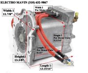
ford_ev_motor_1_7.jpg
 
I wasn't able to find out for sure if the SSD drives used the FOC to get the full torque at zero RPM so if you can find out for sure ie. referenced in the manual or a paper, that would be great.


-Rjay

Ford Siemens motor i think..

Check your PM's
 
Can I ask why you are worried about 100% torque at 0 RPM? For a car I can't really see why this type of control is necessary? I would think a simple V/F drive would be fine. In a vehicle I would be more concerned about being able to regen then I would be about vector control.

BTW I don't think that AB's "force" technology is anything special. ABB's DTC has been around a lot longer and has always worked well.
 
Can I ask why you are worried about 100% torque at 0 RPM? For a car I can't really see why this type of control is necessary? I would think a simple V/F drive would be fine. In a vehicle I would be more concerned about being able to regen then I would be about vector control.
quote]

Allscott
Good point and valid - assuming vehicle is always driven on flat and less than about 30 to 35 mph. Under those conditions he will need 100% of motor torque to breakout and get started.

HOWEVER above 35 he needs to consider windage and add torque to his load's demanded torque.
AND he has to add torque for hills he climbs at chosen speed.
Here in Seattle with the steepest hill at 21% if I design for speed climbing the hill at 30 mph then I will have more than enough torque on motor to overcome wind at 60 mph.

SO load torque = rolling resistance torque + wind resistance torque
OR if hill is steep enough and desired speed is high enough just torque demand on hill.

Regen is "automatic???" with VFD and 3 phase. As example quickly switch a two speed motor from high to lo and see how fast it brakes to run at lower speed - be careful doing this hard on contactors and can tear up driven equipment. Same principle and concept for vfd and motor with overhauling load. the motor will produce braking torque to stay running at command speed. this will feed power back to vfd and to dc bus which will charge battery (which will in most cases eliminate need for brake resistors)
Dan Bentler
 
Last edited:
Allscott, I think Leitmotif covered it pretty well. The changing loads in a car, as I understand it, will cause slip in the motor. Without good feedback via encoder, or synthesized feedback via the sensorless vector, the torque would not be maintained and ultimately, power will suffer. The feedback will also help the rapdid response to load so that the motor continues to deliver power as the road conditions change. I live in Boulder, Colorado and we have a few hills around here too.

Plclatin and alan_05, thanks for the sites. I specifically enjoyed the Danfoss drive on the Suzuki. He used an existing full HP drive ($$$)...I am hoping to modify a little drive (2-5HP) with big honkin' (technical term) IGBTs and make him into a big drive (40-90HP) to drive this beast of a motor that I have :). I just bought an Emerson Unidrive so I am going to give that a try. I really liked their modular approach. Most of the smaller AC drives don't give schematics but I am hoping I can reverse engineer the board and that tracing down the 3 phase power path won't be too hard ;-) The drive ran me $280 on Ebay and it is 240V (7.5 HP).

If anyone can think of gremlins..er problems that I will run into, please feel free to toss 'em out there.

Thanks,

-Rjay

The one thing I keep thinking about is making sure the current sensors are correct size for the load and they have the correct signal to the control board.

Dan Bentler
 
Dan,

280 Amps. See the plot.

Dave,

You are right. I am looking for good current sensors right now. I will have to scale them to what the Unidrive expected. The encoder is a 12V quadrature so should be compatible. So...the drive puts out 3 phase voltage based on PWM output from IGBTs. As long as these are sized and triggered appropriately, I should be ok. The voltage feedback on the output should be the same as it is today. Current is second and then the encoder. It seems conceptually straightforward...we'll see. I just have to make sure that I don't blow up a bunch of expensive IGBTs!

-Rjay

MotorTorque.jpg
 
Oh...yes, I have the motor :). $1500, Ebay. When I bought it, there were 30 left. The very next evening, an electric vehicle conversion company bought the remainder. I guess I squeaked under the line.

-Rjay
 

Similar Topics

Hi, Yesterday, I was at a customer site. I made one little change. Changed a dummy bool output to an actual output. I didn't add any tags, or...
Replies
15
Views
357
I know this isn't PLC related, thanks for bearing with me. Does anyone have an excel sheet to calculate full load amps for branch circuits? Im...
Replies
0
Views
723
Hello, I have rslogix processors operating at anywhere from rev 16.0 to 30.0. I have the full option of FBD routine creation in the higher...
Replies
9
Views
2,854
struggling to find documentation on this, I have it in my head that it overwrites itself but i dont know where i have got that from. when it...
Replies
0
Views
890
Dear experts, I have encountered an SMC Flex (361A,480V) wired for 3-wire where that if you press 'Start' Then immediatly press 'stop' it will...
Replies
7
Views
1,779
Back
Top Bottom