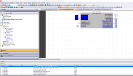
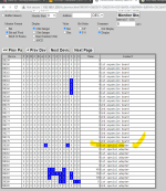
FX3G Analog registers add in card 4ADP

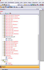
If you look closely at the documentation it does appear that the same module uses different 8000 registers depending on the PLC module, so for example (not a real one) If FX3UC uses D8020 the FX3G uses D8120 that is why I do not believe the FB's in the library will work on the FX3G as there are many FX versions of the FB but not one for the FXg series. as per picture
These FB's are pretty simple if you use the standard analogue modules that fit on the I/O (right hand side of PLC) then these modules you can use the TO/FROM functions to get the data that are aready installed in the elements selection as standard.
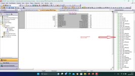
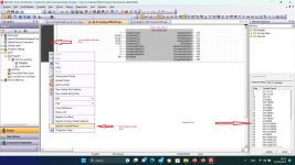
FB's installed.jpg
 
See this, perhaps post me your file to the email I just sent you & I will look at it, I believe the way you are trying to add the FB to another FB etc. it is not being called in the task setting

Compile result.jpg
 
I downloaded the FB lib V320 & it does not contain a version for the FX3g, so I used the FX3U block & the registers are as per manual i.e.
M8260 -3 for the Channel modes for first adapter whereas the FX3G uses M8280-3
Same goes for the Analogue actual values
FX3U D8260-3
FX3G D8280-3
So the FX3U_4AD_ADP only supports the FX3U.
I have searched the Mitsi website & cannot find FB's that support the 3G ?.
 
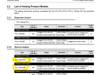
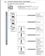
I thgink the modules work with fx3g, shown in the wiring manual and the analog manual, see attached.

I have tried your code from the email, thank you so much. Unfortunately I can't get it to work. I tried different module numbers, true instead of false, nothing. Very frustrating.. It compiles and uploads fine, I can monitor but no action..

I will try everything I can think of but it's getting a bit hopeless feeling now. I really want to make my distributor swap these out for the non P versions that attaches to the rhs of the plc, I have used them before and they are simple..

Again I am humbled by your assistance, thank you.

Monitor window snipped, D8280 is the onboard analog input that is working fine. I duplicated the wiring scheme to another of the same sensors and it is screwed into the first extension module at the moment.

list fx3u.png fx3g ok 1.png fx3g ok 2.png running.png monitor.png
 
I think you are confusing the FB's i.e. FX3U ADP because you are using the FX3U-ADP modules, these can be used on the FX3G but there is no FB's for that model see attached code (I will send you the actual file by email).
It is essentially the same with the supposed correct addresses for the FX3G, I cannot try it as I do not have an FX3G & no analogue cards.
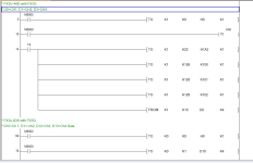
Shown is setting two of the channels as 0-10v & two as 4-20 if you want all the same just add the output coils to either the first or second ladder & delete the other i.e. all to 0-10v or all to 4-20
 
I have sent you the file I created, hope I got the registers correct for the FX3G you may want to reset all the error bits i.e. add the rest of the reset coils M2-M11 as I have only done the ones for two of the channels m12-15 are not used.
Note: as I said in the comments FX3G will not address at bit level in D memory so copied the data in the error status D memory to bits then just reset the M bits & transferred it back, this only resets the error status bits on first scan on a re-start of the PLC.
 
Another thing to keep in mind, is that the FX3G has two inbuilt analogue channels these are dedicated to M/D8280-1 etc. so this may cause a concern and require the FX3U_4AD_ADP to be treated as the second and not the first analogue special adapter and referenced accordingly.
 
Yep that is possible, on the 3G you can only add two adapters of the FX3U ADP so it could be these are 3 & 4 as far as the registers are concerned but in the manual they are shown as 1st & 2nd

The code I posted accounts for this so should work
 
I have sent you the file I created, hope I got the registers correct for the FX3G you may want to reset all the error bits i.e. add the rest of the reset coils M2-M11 as I have only done the ones for two of the channels m12-15 are not used.
Note: as I said in the comments FX3G will not address at bit level in D memory so copied the data in the error status D memory to bits then just reset the M bits & transferred it back, this only resets the error status bits on first scan on a re-start of the PLC.

I think you are confusing the FB's i.e. FX3U ADP because you are using the FX3U-ADP modules, these can be used on the FX3G but there is no FB's for that model see attached code (I will send you the actual file by email).
It is essentially the same with the supposed correct addresses for the FX3G, I cannot try it as I do not have an FX3G & no analogue cards.
Shown is setting two of the channels as 0-10v & two as 4-20 if you want all the same just add the output coils to either the first or second ladder & delete the other i.e. all to 0-10v or all to 4-20

Ok, firstly thank you!

Now I can reset the D words in that range manually from the gx works 'modify value', this shouldn't work right?

I have tried your ladder with all the combinations of addresses and stillc an;t get anything to change. Error words are all at 0 but no response. I am 3000km away so I think next step is sitting in front of it and testing every input on the cards and every output until I find something that works..

Pretty disappointing that the manual is absolutely not correct, I have so many hour sin this it is crazy and I have got nowhere, this should be a simple thing..

Thanks again, will close the loop here if I ever do figure it out.

Muz
 
I do agree that sometimes the manuals have errors in them but I would think it is unlikely, it's a pity I do not have a 3G & the adapters, only used them on a FX2N & never had any problems but obviously with the 3G having built in analogues i.e. cards 1 & 2 I would have thought that the registers shown in the manual are correct. I assume the version of the FX3G is at or above the versions shown in the manual but it does seem that the 3G series will work from the initial version. I assume you have 24v power connected etc.
 
Ok so to close this out bar one step. I gave up on the 4ADP cards and went to the 4AD and 4DA cards that I have used the digital version soff. Faced basically the same problems.. Ended up with my plc supplier helping me out. This is the program;

Notes:
CPU - 4DA-4AD

Simply change the Hex Value in the first line to the mode you want for each channel, do it for both the input and output module (is currently set for voltage out and in)

fx3g 4ad 4da.png
 
Yep these cards have greater functionallity than the ADP addon ones they have buffer memories (BFM) you set the required modes by setting the required buffer memories the main one is the input type i.e. 0-10/4-20 etc. this is done normally on startup of PLC just once before the scan of the rest of the code using M8002 (first scan) there are other parameters as shown where they write information but to be honest there is not really any need to change them for simple A/D conversion then in the case of the code you show they read the values of the buffer memories containing the analogue values into D memories.
The same goes for the D/A but if you like in reverse. It makes sense to download the specific manual for those cards as there are loads of BFM locations for example Offset & gain parameters, averaging etc. most can be ignored TBH I only tend to use the setting of the input/output type & the reading of the analogs I tend to scale the raw values in the plc code i.e. zero & span so do not use the offset & gain settings in the card.
 
I seem to remember that you are using GXWorks2 so perhaps convert it into FBD/LAD as it is a far better tool for documentation I have shown this as attached but only for the analogue inputs.
 

Similar Topics

Good Evening, I am an under graduate engineering student presently working on a project involving the Mitsubishi FX3G PLC. I plan to programme...
Replies
7
Views
8,482
I have encoder connected to FX3G and stepper. What I want when I rotate encoder it moves stepper. Encoder sets position for stepper. Or each pulse...
Replies
14
Views
2,200
I have a client with a Mitsubishi FX3G-60MT PLC the machine is Chinese only 5 years old and surprisingly its build is good. however.... its PLC...
Replies
10
Views
3,380
Hello Friends I need to communicate these devices. Is it possible? How can I do that? The marker supports RS232C and Ethernet, which could be...
Replies
3
Views
1,135
Hi all, I am totally new to the PLC world and I already face a major obstacle :) I am trying to control a really simple pneumatic system using...
Replies
1
Views
1,458
Back
Top Bottom