GX developer: what's the difference between a coil and a SET/RST?

Yes, it's a neat piece of code. Widely used, I imagine.

snort. ya' think? ;)http://www.contactandcoil.com/patterns-of-ladder-logic-programming/

In my original post, the operator wants to be able to control the fans in one of two ways: manually (fans on/off whenever they please) and automatically based on water temperature - if it gets to integer 300 (30 celsius) turn it on, when it's below 30c turn it off.

same pattern, (i.e. start, stop, run/seal-in), but the start and stop booleans are compound expressions e.g.:

start: (auto AND low_temp) OR (not_auto AND operator_button_pressed)

stop is more interesting cf. DeMorgan at this link
 
Last edited:
if it gets to integer 300 (30 celsius) turn it on, when it's below 30c turn it off.


If this is indeed bang-bang control, you might want to put some hysteresis between the turn-on and turn-off limits, although with temperature it may move slow enough and/or have enough inertia that it does not matter.
 
That is the main difference in approaches. Do you need to "remember" the output's last state if the controller loses power / is shut down? If yes, then latch.

The answer to this is yes - we want to remember the output's last state after a power interrupt. I think that's why SET/RST has been extensively used throughout the code.
And yes, I'm using Mitsubishi PLC.
 
As an auxiliary to this topic, using a "SET" or Latch on a physical output is a questionable programming practice. Consider all potential safety hazards. Data can be maintained even if the PLC is dormant for a period of time. Just my .02!

The practise is fine, it's the thought process behind it that can be questionable.

For instance, some this absolutely must restart by themselves after say a power fail, other things absolutely must not.
 
Ot

OT - TL;DR

that is the start/stop cursor pattern.

that is functionally equivalent to a set/reset pair*, with the exception that it will always return to 0 on a mode valance or power cycle.

*
[> D353 K800] => [SET Y2D5]
followed by
[<= D353 K240] => [RESET Y2D5]


Changed and to followed by., because that is important.

Reversing the order, i.e. [clear_fault_condition => RESET] followed by [fault_condition => SET], is similar to the Start/Stop circuit pattern (cf. this link) in that it has a seal-in, but the (not-)stop condition moves to the seal-in branch, and is called the State Coil/Fault Coil circuit pattern (cf. this link). The distinction is sometimes made via the phrases "stop dominant" and "trigger dominant."
 
The answer to this is yes - we want to remember the output's last state after a power interrupt. I think that's why SET/RST has been extensively used throughout the code.
And yes, I'm using Mitsubishi PLC.


Nuance it a little more, for example "we want to remember the outputs last state and if all the conditions to turn it on are true the it will turn on otherwise it stays off"
Meaning on startup it all outputs are reset and the logic determining their state is evaluate.
And "remembering" the state of variables or physical outputs can be achieved using either methods, I do not understand why the use of SET instruction is always tied to this "remember" thing.
 
Last edited:
OT - TL;DR


Changed and to followed by., because that is important.

Reversing the order, i.e. [clear_fault_condition => RESET] followed by [fault_condition => SET], is similar to the Start/Stop circuit pattern (cf. this link) in that it has a seal-in, but the (not-)stop condition moves to the seal-in branch, and is called the State Coil/Fault Coil circuit pattern (cf. this link). The distinction is sometimes made via the phrases "stop dominant" and "trigger dominant."

Great, thanks for the correction and the extra information. Much appreciated.
 
I do not understand why the use of SET instruction is always tied to this "remember" thing.


Because not all PLC brands implement "remembering" in the same way, and many consider the way "their" default PLC act is normative. This thread reminded me that this is an important consideration: not all PLC brands "remember" the state of SET (Latched) bits across mode changes. I would think the best thing to do would be to repeat an experiment similar to @Ron Beaufort's so one on one's own hardware can definitively know how that particular PLC will act.

In Allen-Bradley (A-B) PLCs, if a bit is Latched (via OTL instruction*; i.e. SET in non-A-B jargon)) when power to the PLC is lost**, then on return to the RUN mode*** that bit will be 1 at the start of that first post-non-RUN scan.

* cf. this link and this link;
** or the PLC goes into PROGRAM mode
*** E.g. when power is restored, if PLC is configured to return to RUN mode in that event


Thanks drbitboy, I may (though very unlikely because it's AB) a look at the links later, doesn't that have to do with the memory structure rather than instruction. The instruction sets to true/moves 1 /inverts /latches however it may be called, it is a function of retentive memory not the instruction itself, meaning one would achieve the same result with MOVE or bit masking, just two examples? I understand that AB memory is all retentive and that may be the cause of confusing the functionality of the instruction with memory retention.
 
Mitsubishi is slightly different, for example on FX Processors if you use an output i.e. SET it then switching to STOP will reset the output so if the condition to set the output coil is not true but the output coil is set then when switched to stop & back to run the coil will reset, however, on the simulator a Q type PLC the output will stay latched when switched back to run (not sure this happens on a real processor though), TBH if any PLC I code I rarely have any outputs automatically return to true without operator intervention, there are some exceptions but rare.
Many PLC's will not re-energise an output or internal memory bit to it's original state unless that memory is retentive i.e. latch type.
 
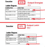
See images from Logix 5k instruction set manual below; RSLogix 500 is similar, IIRC.

The implementation in Allen-Bradley of how a bit acts across a mode cycle (Run=>Program=>Run, or a power cycle) is tied to the Prescan and Postscan behavior of any instructions that write to that bit.
xxx.png
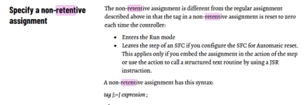
For Structured Text (OT: what a ridiculous name), there is also the issue of retentive vs. non-retentive assignments.
yyy.png
 
The instructions OTE and OTL are what we already know and similar in how they execute to other platforms. Which means that the difference in how the BIT behaves on PLC COLD or WARM start, is PLC and Memory dependent.
The Structured Text ( as opposed to unstructured text) is different in that non-retentive may be determined individually in code; I've never see this before. But that's where the difference ends, how the instruction (assignment) behaves is as expected and the same as other platforms.
 
This thread was posted as per Mitsubishi hardware & how it works regarding retentive states so the following applies.
On Mitsubishi outputs are switched off when in stop, however, on the Q series it does appear that on a stop to run if the output coil was set before stop it will return to on if set previously, I can only try this on the simulator as I have no I/O on a Q PLC, on the FX if the output was set then put into stop it will be reset & not go back to true unless the logic driving it is true, this applies to all non retentive memory bits so Y (outputs) M internal memory and others like D L, B etc. Y, M cannot be set to retentive like L, D etc. So on a Q processor it does appear if put to stop the bits are retentive as although in stop mode they are false, it must map them into some retentive area as when switched back to run they go back to the state that was inn run, if the processor is powered down then a latched output or an internal M bit will not return to true.
So in short:
On FX models outputs & memory "M" bits will not retain their status if switched to stop or powered down.
On Q series, the outputs & M bits will go false when in stop but are set back to their status before the stop condition, if the PLC is powered down then these will loose their status & all be false.
The only way is to map them into retentive memory every scan & hope this is enough when re-powered restore the mapped bits back on the first scan.
 

Similar Topics

So far, for adding new rungs I've been using INSERT LINE, but I notice that INSERT ROW is also in the drop-down list. So, what's the difference...
Replies
10
Views
3,598
I'm trying to verify a project with a PLC. The Transfer Setup menu item is grayed out and every time I click Verify with PLC, I get an error...
Replies
1
Views
51
Well, I've decided to start a new project, and like all projects, it has already gone horribly wrong. I purchased a PLC device (supposedly a...
Replies
2
Views
111
Does anybody have any samples of how to "Create and Use" UDT's in CCW Developer Edition? (I am using v22) I can't find any information from...
Replies
3
Views
313
I'm trying to manually convert a Beijer E200 HMI project onto to a new Mitsubishi GOT gs2107-wtbd. The PLC is a very old A-series AS1CPU and is...
Replies
1
Views
382
Back
Top Bottom