Help:sequence Control Circuit

I have already a Zelio logic control with 8 digital inputs and 4 digital outputs and I will search in this topic to any ladder diagram to do it.
First make an outline of the program, listing all of your Outputs (Q1, Q2, Q3 for Pumps 1 to 3, Input I1 to I3 for your 3 Pressure Switches, Input I4 for a Reset Pushbutton, Internal relay bits M1 to M9 for your Pump Sequence Bits, and Counter C1 for the Pressure Switch Counter).

Looking at the instructions available for the ZelioSoft Ladder programs, there are no indirect addressing, or sequencer instructions. But there are Counters and Counter Comparators, so use a Counter (as mentioned by Garry way back in Post #2).

Pressure Switch Counter 1: Counts from 1 to 9 as the Pumps come ON then go OFF (Each of the 3 Pressure Switches cuts On then Off to trigger the Counter). The Pumps follow a sequence controlled by 9 "M" internal auxiliary relays (M1 to M9), then repeats.

1. When C1 = 1, M1 is activated (which runs Pump 1).
2. The next pressure switch activation moves the counter C1 to 2, and when C1 = 2, M2 is activated which starts Pump 2.
3. When C1 = 3, Pump 3 runs.
4. When C1 = 4, Pump 2 runs.
5. When C1 = 5, Pump 3 runs.
....(and so on up to step 9).

Each M relay runs a pump, until 9 runs are completed (M1 to M9). The 3 pumps will run in order controlled by a Pump Number sequence: Pumps 1, 2, 3; then 2, 3, 1; and then 3, 1, 2; then repeat the sequence as controlled by M1 to M9.

When Counter C1 = 9 and the pressure switch opens again, then the Counter and all control bits are reset to 0, and the cycle repeats.

Usually at this point, the beginner comes back and says "I forgot to mention that it needs to do this . . ." Now is the time to reveal all details. Going farther without the full infomration will lead to disaster (a non-working program).

Adding logic so that if a pump Overload is tripped or a breaker is off on one pump the run logic will be passed off to the next pump in the scheduled sequence is optional, but it will be very usefull if I do it.
Bonus Points? I suggest you use a timer set for about 5 seconds to determine if a pump has started. You will need 3 additional Inputs (I5, I6, and I7?) from the Pumps to determine if the pump started when told to start. If not, advance your C1 Counter by 1 using a M relay "Active on impulse relay edge" (or one-shot pulse) to start the next pump in the sequence.
 
Last edited:
Would this work? The pressure switches can be in the main pressure line and this only works if one compressor can supply the demand. The low pressure switch and high pressure switch need to be de-bounced for at least a few seconds.

pumps.jpg
 
Good try, Rocksalt. It would work in many PLCs, but the ZelioSoft that Eslam Marwan said he had to use is limited - no accessible memory words, no built-in one-shot instruction, no Move instruction. The Zelio only has 8 Counter Comparison bits (where you can compare a Counter value to be =, <, >, <=, >= to a Constant number. This project is set up so that it uses 1 more step than there are Counter Comparison bits! That means the logic has to use the 3 Pressure Switch inputs in combination with 5 Counter Comparison bits to get the desired results.

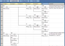
Here are lines 11 to 19 (out of 30) for my ZelioSoft version of his program. I made one-shots (using"M" relays) for each pressure switch, to trigger a Counter that counts up to 9. The pressure switches (in combination with Counter Comparison bits) are also used to turn on Step Relays from M1 to M9. It is my understanding that the Pressure Switches will go ON in order: PS1, PS2, then PS3, then go OFF in reverse order: PS3, PS2, then PS1. When all 3 Pumps are again OFF, then the next cycle should start. For each set of 3 pump runs, the order advances by 1 Pump, so that after 3 sets, (9 pump runs) the cycle repeats.
After all pumps switch off and at the next start the sequence must be Pump2, then Pump3, then Pump1.
Each Pump Output will then be controlled only by the RUN Mode contact and 3 parallel Step Relays. Pump 1 has Step relay contacts M1, M6, and M8. Pump 2 has Steps M2, M4, and M9. Pump 3 has Steps M3, M5, and M7.

Three-Pump Sequence Control Sequence- Lines 11-19.jpg
 
Last edited:

Similar Topics

to all PLCS gurus, pardon a question from a newbie.. 1.) A conveyor will be controlled by a motor speed controller, to be specific a gear motor...
Replies
7
Views
4,850
Hi guys I’m after some ideas to display a weighing system on a hmi to help with easy fault find? We have a micrologix 1400 and pvp 700 all on a...
Replies
7
Views
2,361
I am currently taking PLC training and have come across a circuit that I can not figure out how to complete. Any help would be greatly...
Replies
8
Views
2,076
Hello,Can anyone help me with this program I'm trying to develop? I'm using a AutomationDirect CLICK plc. Sequence will start and stop using a...
Replies
24
Views
13,260
Hello, I have to leave my Schneider PLC for a little job with an S5 and it is giving me a hard time: This is the FB11, it is called by another...
Replies
4
Views
3,734
Back
Top Bottom