Helping with my final project

alketbi

Member
Join Date
Feb 2013
Location
Dubai
Posts
8
Hi guys
I need help from you
this is my last year in the university and I have a final project which is automatic controlled system

here you can read the Principle of Operation of my project :

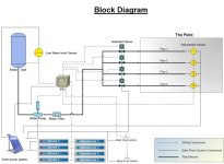
(you can see the diagram)

The Concept of this project starts from the field where there are some soil moisture sensors and it begin when the soil gets dry the soil moisture sensors will sense the moisture in the soil and the sensors will send signals to the PLC for taking an action and the Dry soil LED will be on to show that the field need watering. The PLC will activate the water pump and PLC will choose the water path by opening the solenoid valve for the needed field. On the other hand, The PLC will not operate the pump unless there is enough water in the tank. By using a level sensor otherwise the water pump will burn if the tank is empty. Moreover, when the soil gets wet the soil moisture sensors will sense that and that will be shown in the saturated indicator LED. Also, the Start and Stop Push buttons will be exist to active and stop the system.

the problem is how I can do the ladder diagrams for PLC???!!!

and I have 7 inputs and 12 outputs, what is the best plc module should be used ( I mean the fixed or the small plc ) and how the connections will be ?

Really I need help from you I have every thing expect the programming.
IIS.jpg
 
First off. If you're asking whether you should use an actual PLC or a smart-relay-type-PLC, then my suggestion is using an actual PLC. For instance, an Siemens S7-1200. If I've understood this forum correctly, that's one fine PLC. If I'm not mistaken, there should be some available that has 12 outputs. Depending, of course of the kind of output. otherwise, extensions are quite managable.

Secondly, what is the reason for your desire to program the PLC with ladder? Specification in the assignment, or your own experience? I prefer any and all language but ladder =P

And as far as the program itself. It seems fairly simple. (dry sensor AND NOT Low Water)=Open needed solenoid valves + timer
((solenoid valve 1 OR 2 OR 3 OR 4) AND timer low)= Start pump
And as far as LED's go, dry sensor=LED dry sensor. NOT dry sensor = LED Saturated sensor

Why don't you get started with an attempt, and we'll fill out the blanks if needed? ^^

Thank you for fast replying

first of all I want to use the smart-relay-type-PLC (in 12 V), because the whole system will be run by solar power system

secondly, I think it will be easy if I programmed the system in ladder diagram for example by LogixPro, then put the program in the smart-relay-type-PLC.

This is what I am thinking about !!!!
 
If you're going to run the system from solar power then power consumption should be your primary concern for the choice of smart relay vs PLC. Having said that, the power required by the pump and the valves will be far more significant!

How about starting by naming all your inputs and outputs. Then, for each output, make a list of what the conditions are for the output to be on. Post your results here and people will be able to offer advice.

Nick

The pump that I am going to use is DC 12 V approximately 160 watts, the solenoid valves will consume low power ( just a relay on- off )

The inputs of the system will be :
4 Soil moisture sensors
1 water level sensor
2 push buttons

total 7 inputs

The outputs :
4 solenoid valves
4 dry soil LED indicators
4 wet soil LED indicators

total 12 outputs
 
the problem is how I can do the ladder diagrams for PLC???!!!

This is a very easy logic to make in Ladder.Give it a try and post your effort here.After trying, tell us exactly which portion of the logic you are having trouble constructing and we will help you.
🍻
 
That's good and all, but I suspect what Nick meant was to give each their individual name, I.E. Soil_Sensor1, Soil_Sensor2, Soil_Sensor3 and Soil_Sensor4. This will help plan the system, using Nick's method of listing conditions. Much like I proposed, it would look something similare to th... hang on. How come you haven't listed the pump as an output. Did you forget, and that makes it 13 outputs, or are you planning on starting it somehow differently?

Anyway - condition list:
start "Pump" IF ((Soil_Sensor1 OR Soil_Sensor2 OR Soil_Sensor3 OR Soil_Sensor4) AND (Solenoid_Valve1 OR Solenoid_Valve2 OR Solenoid_Valve3 OR Solenoid_Valve4))
and so forth. Give it a try, in whatever way is easiest for you to understand =D
 
This is a very easy logic to make in Ladder.Give it a try and post your effort here.After trying, tell us exactly which portion of the logic you are having trouble constructing and we will help you.

🍻

I will be honest with you
I'm not expert in plc I have just a littile information

there is one student did such as this project but simpler (you can see the ladder diagram of his system)

I don't know if I should do the programming from zero or start from where he has done?

plc.jpg
 
See? Now we're getting somewhere. I'd say - look at his diagram. Inspect every component and learn from it. When you trust you've understood his diagram, start your own from scratch.

When you've gotten som ground laid down, make the diagram as far as you can with your knowledge. If you run into some problem, or just can't get it to work, post your solution so far and ask us for help. That's the best way to learn something =D
 
Forget the PLC at this point and concentrate on the logic such as:

Output_1 = input_1 AND input_6 AND NOT input_3

That is why is is useful to give inputs and outputs a meaningful name.

Nick
 
The most import this is understanding what inputs/outputs you have available and as Manglemder said name them e.g. Valve_Open_Output
When working out the logic break the project down into small parts. At this stage forget about fields 2, 3 and 4 concentrate on field 1, the others can be added when you are sure field 1 works correctly. If the motor has more than 1 signal then you can look at that as a small part of the project for example available signals, Pump_Run_Output & Pump_Running_Input.
Slowly build up these sections, link them together and test them as you go.
Let us know how you get on.
 

Similar Topics

hello i'm not good at english, please understand i just found this website from googling, while i was looking for how to use program(from m340)...
Replies
4
Views
531
Good Evening , This sound like a strange idea. This has been on my mind and heart for several years. We have a homeless and drug issue in...
Replies
4
Views
1,864
Hi guys, Working on one of my client's systems with SLC processors, earlier today she called me and said she was having comms errors, had a solid...
Replies
5
Views
2,041
I'm newbie in PLC and I face couple problem in SCL(194) instruction. The problem have wrote to the pictures kindly tutorial me how to do it...
Replies
15
Views
10,669
Could you please explain what does " fe , re , dec" means if fe (Mixing_done) then feeder_state:=material_a_value+material_b_value; reset...
Replies
7
Views
3,215
Back
Top Bottom