Hi friends;
I am new witth that speed sensor. I want to simulate the speed signal plz guide me how can i simulate it? I have Fluke 741B and frequency counter as well.
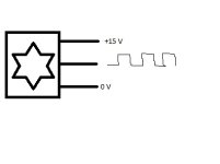
The data of Speed probe is as under
60 pulses per revoulation
Supply Voltage +9.5 to + 15 V
Power consumption 40 mA
Tranducer Type MDg 14 Output signal +12 Volt depend on the supply voltage.
Range of working frequency 1 HZ to 30 Khz
The wiring diaggram is attached with it.
Output is suare wave.
I want to ask how and what value of Volt and HZ i give to simulate 5500 RPM.
Function generator have both options square wave and sine wave.
Which one i apply?
Regards


