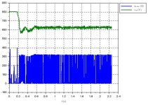
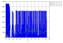
Let's say I have an inverter fed three phase induction motor drive where in the braking phase (when the motor operates in a generator mode) the generated electrical power is dissipated in the braking resistor controlled via simple chopper. Below is a record of the braking chopper operation.

I need to implement a software based thermal protection of the braking resistor. Unfortunately there is no temperature sensor installed in the braking resistor. So I has to somehow estimate the temperature.
My first idea how to do that was to exploit the measured dc link voltage and the current through the braking resistor and calculate resistance of the braking resistor via the Ohm's law. Then I can derive its temperature from the temperature dependancy of the resistance. I have attempted to experiment with this approach but I have received huge spikes of the resistance value. The results aren't much more better neither in case I filter the resistance values via the simple first order low pass filter with time constant 1 s (from my point of view reasonable value)

Does anybody see any way how to get more reliable resistance values via the method I have described above?

I need to implement a software based thermal protection of the braking resistor. Unfortunately there is no temperature sensor installed in the braking resistor. So I has to somehow estimate the temperature.
My first idea how to do that was to exploit the measured dc link voltage and the current through the braking resistor and calculate resistance of the braking resistor via the Ohm's law. Then I can derive its temperature from the temperature dependancy of the resistance. I have attempted to experiment with this approach but I have received huge spikes of the resistance value. The results aren't much more better neither in case I filter the resistance values via the simple first order low pass filter with time constant 1 s (from my point of view reasonable value)

Does anybody see any way how to get more reliable resistance values via the method I have described above?


