Greeting to all,
I seem to never get a handle on motors and their operation and I was reading this WEG pdf which puzzled me.
So we have dual voltage motors that have their winding wired in series or parallel.
Y start and Delta run, motor starting method for certain applications.
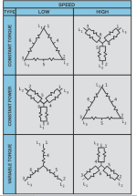
Dual speed (Dahlander) Motors, and that's where things went sideways for me. The wiring illustrations (see image "Page 30") dual speed motors wired for three different applications, Constant Torque, Constant Horsepower and Variable Torque.
Assume we have the same voltage for all (that's my assumption).
Thanks


I seem to never get a handle on motors and their operation and I was reading this WEG pdf which puzzled me.
So we have dual voltage motors that have their winding wired in series or parallel.
Y start and Delta run, motor starting method for certain applications.
Dual speed (Dahlander) Motors, and that's where things went sideways for me. The wiring illustrations (see image "Page 30") dual speed motors wired for three different applications, Constant Torque, Constant Horsepower and Variable Torque.
Assume we have the same voltage for all (that's my assumption).
- Constant Torque low speed:
- Pole pairs are wired in series and the three phases are wired in delta configuration.
- Constant Torque high speed:
- Pole pairs are wire in parallel and the phases are wired in Y configuration.
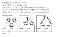
- Question #1: Will the windings in this configuration "see" more voltage? (see middle drawing in image "Page 19")
- Question #2: Doesn't fewer poles (wired in parallel) produce less torques?
- Constant Power:
- The wiring diagrams are place opposite to the one above it.
- The Wye configuration with parallel pole pairs should be the high speed and the Delta should be the slow speed.
- Questions #1: What I missing concerning the speed?
- Question #2: How did it become constant power?
- Variable torque:
- I think I understand this one, they Wye configuration with winding wired in series will drop the current and the torque goes down with it and with Delta configuration we will have less poles(paralleled) and more current meaning more torque, am I on the right track?
Thanks


