Is anyone familiar with AD SureServo PCS digital input position commands?

Join Date
Apr 2020
Location
USA
Posts
50
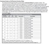
I am experimenting with a very simple program for testing purposes and not getting any movement from the servo motor. The attached program enables the servo (Dig Input 1), sends the command trigger (Dig input 2) and activates an output that is tied to the PCS0 servo (Dig input 5). The PCS0 digital input is connected to parameters P1-17 and P1-18 which I do have Revolution values entered. This should represent Position Command P2 in the attached graphic.

Through tech support at AD, they helped me confirm the servo is in fact enabled and seeing the command trigger along with the PCS0 command (visible through servo drive display command P4-07). As another test, I switched the servo digital input parameter from PCS0 to JOG. This test works and the motor will JOG.

It appears I am missing something with the PCS0 command. In the attached graphic last sentence, it says the PCS commands are activated on the "rising edge" of the command trigger. Can someone explain what this terminology is referring to?

RSlogix file is "Servo PCS Command" change from .zip to .rss
PCS command detail.JPG
 

Attachments

  • Servo PCS command - Copy.ZIP
    44.5 KB · Views: 4
I am experimenting with a very simple program for testing purposes and not getting any movement from the servo motor. The attached program enables the servo (Dig Input 1), sends the command trigger (Dig input 2) and activates an output that is tied to the PCS0 servo (Dig input 5). The PCS0 digital input is connected to parameters P1-17 and P1-18 which I do have Revolution values entered. This should represent Position Command P2 in the attached graphic.

Through tech support at AD, they helped me confirm the servo is in fact enabled and seeing the command trigger along with the PCS0 command (visible through servo drive display command P4-07). As another test, I switched the servo digital input parameter from PCS0 to JOG. This test works and the motor will JOG.

It appears I am missing something with the PCS0 command. In the attached graphic last sentence, it says the PCS commands are activated on the "rising edge" of the command trigger. Can someone explain what this terminology is referring to?

RSlogix file is "Servo PCS Command" change from .zip to .rss


rising edge refers to a digital signal being activated.

falling edge refers to a digital signal being deactivated.


edge.png


imagine when you press a button that activates an input. when you press and hold, you have a rising edge signal, the inputs goes high and stays high.

when you let go of the button you have a falling edge signal, it went from high to low and stayed low.

for every momentary press you have a rising followed by falling, which defines a momentary digital input.
 
It appears I am missing something with the PCS0 command. In the attached graphic last sentence, it says the PCS commands are activated on the "rising edge" of the command trigger. Can someone explain what this terminology is referring to?

As pointed out by @IanM8040, a "rising edge" is referring to a transition of the AD input of "off" to "on."

Note that the same idea is expressed in a Note at the bottom of the JPEG you attached:
3) The position command is activated by an Off to On transition of the Command Trigger DI.
What this means is that the Command Trigger (B3:1/1 => O:0.0/1 => DI 2) needs to transition from 0 to 1 for the [DI PCS1/2/3] bits to be interpreted by the servo, and the servo to move to the specified position.

The purpose is so that, as long as the Command Trigger is off and/or does not change, you are free to change the [DI PCS1/2/3] bits to the next position without it having any effect on the servo until the servo detects the Command Trigger edge.

I am only guessing, but may be that the DI Enable (B3:1/0 => O:0.0/0 => DI 1) needs to be 1 for some (brief?) period before it can detect, and respond to, the rising edge transition of the Command Trigger DI 2. With the logic you have now, those two outputs come on at essentially the same instant.

I've witness some odd issues where the transition from off/on/off didn't occur as expected in the drive.

SEW to be exact, where the drive receives an index command, and then never responds to another index command. Turned out the threshold for a rising/falling edge was extremely small for it. they would send 24v to the drive input, and when they released the 24v signal it kept getting a very small voltage, around 1.2Vdc, never dropping to 0 completely.

It was going through a prox sensor that was obviously using solid state switching (pnp) to send 24v out to it. To alleviate this an interposing relay had to be put in between.


What I'm getting at here is we found that some drives/PLC dont need an exact voltage to consider something a rising or falling signal. and if you have a voltage present on that DI during startup, it may be looking for a transition from low/high again before allowing it to index.

I would try removing the wire from the DI physically, then touching it to the input while you have the signal on it and see if you get a different reaction, it may be electrical and not programmatical.
 
Thanks for the feedback. I've got a few things to try next week, and i'll report back.

For more detail, I am using an AB Micrologix PLC to communicate to the servo drive.
 
Last edited:
rising edge refers to a digital signal being activated.

falling edge refers to a digital signal being deactivated.


View attachment 63492


imagine when you press a button that activates an input. when you press and hold, you have a rising edge signal, the inputs goes high and stays high.

when you let go of the button you have a falling edge signal, it went from high to low and stayed low.

for every momentary press you have a rising followed by falling, which defines a momentary digital input.

Thanks, this graphic explains it well!
 

Similar Topics

Hello, Hoping there is someone out there knowledgeable with GE S2K series motion controllers. The actual model is an IC800SSI104D2-DE. It is...
Replies
0
Views
1,108
I'm looking at bidding what seems to be some standard pump controls for a local levy. The one thing that is giving me a bit of grief is this part...
Replies
19
Views
5,575
Some time has passed since this thread about Thingworx. Any update in light of news of the Rockwell $1B investment in PTC. This video glazes over...
Replies
4
Views
2,547
Looking to put a current transducer shunt on a line with the mV reading going directly to a PLC. Using the ABB S800 modules. From what I...
Replies
1
Views
2,352
I installed Drivewindow Light 2 v.2.92 and am having trouble getting fully connected to an ABB ACH 550 drive. I made an adapter following this...
Replies
3
Views
5,792
Back
Top Bottom