LADSIM Program help

Crumpet

Member
Join Date
Mar 2022
Location
Wales
Posts
5
Hi all,

Firstly I am a complete novice with plc, just started a course so I know this problem is super basic for those with any experience. I have been given a simple timed light program which I need transfer onto LADSIM to simulate. However a number of the symbols don't match up in LADSIM. Would anyone be kind enough to modify the diagram so that it can be copied into LADSIM? It seems the format is different and it's really throwing me off. I've attached the diagram below. All the best
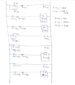
Screenshot_20220301-223008.jpg
 
So what about LADSIM is throwing you off? Because it would be better if you converted it yourself. It looks like the program was written for AB hardware.

What symbols don't match? Because it looks like you have 4 altogether.

-||-

N.O Normally open
-|\|-

N.C Normally closed
-()-

Coil
and TON, which is Timer on delay.

We don't like doing homework for you, we'll help you get the right answer so you learn.
 
Symbols was the wrong word, should have said functions that ladsim doesn't appear to have. For example, ladsim doesn't have a timer timing relay nor B3 which I believe is AB yes. Not looking for anyone "to do homework for me" as the program is already written, that should be quite self evident. Just looking for some help understanding the conversion so I am able to simulate it with what's available to me..
 
I took a quick look at the LADSIM simulator. The LADSIM equivalent to the TON instruction appears to be the TMR instruction. I don't know if or how LADSIM presents the .DN and .TT bits associated with each timer. You'll have to compare the LADSIM documentation with the Logix documentation to figure that out. The Logix I:0/x and O:0/x bits are inputs and outputs in LADSIM. The Logix B3 bits are internals in LADSIM.
 
Quick look is that they also have .dn bits for the timers too.

Well let's start with the inputs, we have I:0/0 and I:0/1. which would be the first 2 digital inputs on the first slot, what's the equivalent to them in ladsim?
 
OT but a good opportunity for learning:

Depending how LADSIM works, there is probably no need for the -]/[- T4:3/DN instructions on the feeds rungs to the TON/TMR instructions for T4:1, T4:2, and T4:3.

The timers are cascaded i.e. stacked: T4:1 starts after T4:0 expires, T4:2 after T4:1, etc..

So when T4:3 expires, then


  • T4:3/DN will become 1, and
  • the -]/[- T4:3/DN instruction on the feed rung to T4:0 will evaluate to false
    • and reset T4:0,
  • so T4:0/DN will become 0,
    • and reset T4:1, ...
and so on up the stack.

Having them there does no harm, but it does make the code more cluttered than it needs to be and harder to read when doing diagnostics.
 
inputs IP ( AB = I, Mitsubishi = X, Siemens = I or E)
Outputs OP(AB = 0, Mitsi = Y, Siemens = Q or A)
flags F (Auxiliary Relays) (AB = B, Mitsi = M, Siemens = F or M)
Timers T (for most either T or TON (turn on) probably only ones on the sim)
Counter C (these can be used count up or count down) (CU CD, C, CNT etc.
The simulator is very basic but this should get you started.
 

Similar Topics

Hi everyone, I have to complete this exercise using LADSIM: http://www.plctalk.net/qanda/showthread.php?t=80080&page=4 This is how it is...
Replies
40
Views
7,574
Hi everyone, I have started on a questIon involving a bottling plant using LADSIM. However, so far, I can only fill one bottle. I am...
Replies
40
Views
12,777
So basically im programming for my studys on the ICT3 via ladsim. I have everything sort of working but the method in which i have used for...
Replies
4
Views
2,342
Hello I'm studying engineering via a local universities distance learning program. I'm currently studying the PLC module and this means some...
Replies
4
Views
2,580
I have been trying to complete a PLC program in Ladsim 3 for the Bytronic Industrial Control Trainer. I have managed to complete the first part...
Replies
1
Views
2,291
Back
Top Bottom