Memory map of omron cpe1 plc

Srini1785

Member
Join Date
Jun 2020
Location
Bangalore
Posts
5
Hello,

I want to understand the memory mapping of a CPE1 Omron PLC. Which areas are accessible and generally operate like a flag bit.

Second, Can we call the same output , say 100.0 in multiple subroutines?.

Sorry if this is trivial. New to OMRON programming environment.
 
Here is the manual section 2 is the memory allocation
https://assets.omron.eu/downloads/manual/en/v2/e480_cp1e_users_manual_en.pdf
Using bits as coils (output instruction) multiple times is not recommended (and probably will cause a compile error on some PLC's) the state of a coil will only be at that state until the next instance i.e. if it = true on rung 1 then was used again on rung 20 but was false then it will only be true between rung 1 & 19 as it will be turned to false on rung 20 and stay that way until the next instance or when the scan returns back to rung 1. The exception to that is if you set or reset a coil multiple times i.e. it could be set on rung 1 if the logic is true and reset on rung 20 if the logic is true. One of the problems in using an out coil multiple times (if allowed) is that when monitoring the program it will depend on when the status is updated on your PC it could be on, however, it is being turned off in one of the rungs.
Example:
PLC Scan....
Starts at rung 1 and ends at rung 400 then returns to rung 1 (normal type of cyclic scan) communications is updated at end of scan. so if an out instruction is true at rung 1 but turned off at rung 200 then when the comms updates the status the status of the coil is false, however, monitoring rung 1 it appears the logic indicates it should be true but the status says it's false.
You can see in this pic, rung 1 has the two contacts that are true, however, the output coil is showing false, this is because the coil is also used on rung 2 where the logic is false so is turned back off, the monitoring is done after the logic scan so will show rung 1 as false even though at that instance it is true.

Coils.png
 
Here is another example, The coil M20 is energised by the true logic of M0 & M1, however it is showing false, on rung 2 M20 is actually true as it has been true on the first rung but is showing false but it must be true as it is enabling M21 to be true, then it is turned off again on rung 3 as M3 is false.

Coils1.png
 
Thank you for your reply. I understand that the conditions should be mutually exclusive for ON logic to work while referring to the same memory bit.

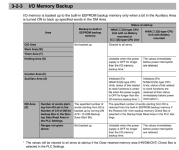
I wanted to specifically understand the usages of W, H and D type memory words in CPE1 PLC. From what i understand, H looses its value when power fails while the other two retain them.
 
Here is the memory map and conditions for retentive memory I do suggest you read the full manual, however, it appears that D areas can be selected for retained memory

Omron.png
 
+1 Parky
"I wanted to specifically understand the usages of W, H and D type memory words in CPE1 PLC. From what i understand, H looses its value when power fails while the other two retain them."
W - Work Area - Non-Memory Retentive
H - Holding Area - Memory Retentive
D - Data Memory - Memory Retentive

Regards,
 

Similar Topics

Hi All, New to Omron, looks straight forward (usually I do Siemens and AB) apart from one simple thing, for the life of me I cannot find any...
Replies
7
Views
12,694
So I am writing my first RSL5k program and I don't really have any guidance or direction on this one, so I have been ferverently reading. What is...
Replies
2
Views
1,500
The conversion goes well except for this: A DB 31 L MB 195 SLW 1 T MW 202 L KH E43E <--- Where is this in the 943 memory LIR 0...
Replies
7
Views
3,315
Does anyone have any experience with Easybuilder using memory map master driver communicating to a CPU board via RS232. Is there any way to...
Replies
0
Views
1,427
Anybody please who's done linking to a.m. flame detector amplifier, can help confirm register address and data format/range for the following...
Replies
8
Views
4,433
Back
Top Bottom