Micro850 ASCII Buffer Not Operating Properly

japes393

Member
Join Date
Aug 2023
Location
The US
Posts
4
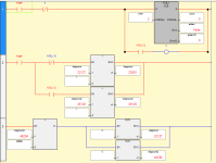
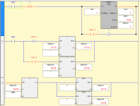
I've been developing a tester using a Micro850 in Connected Components Workbench and part of that tester requires me to scan a barcode every test cycle to know which tests to run in that cycle. When I want to read what's in the buffer I use an ACB block to count the characters in there to both check to see if it's the correct length for a test as well as feed that length into an ARD block if the length is correct. The ARD block reads what's in the buffer if the length is correct and sends that info to the rest of the program to parse which tests are required. An ACL block clears the buffer regardless of whether or not the barcode length is correct and then it's ready for another testing cycle.

From every bit of documentation and online examples what I have seems to be a pretty standard way of doing something like this, but I'm running into some problems with clearing the buffer when the length is not correct. If the buffer length is either zero or the correct length for the ARD then things work perfectly. However, when I feed a non-zero incorrect barcode into this system, the buffer no longer gets cleared until I power cycle the PLC. I set up a testing environment that distills down my program into just counting, reading, and clearing the buffer seen below.
sAuhrwPLxJuD.png

6657pVKPffrx.png

I manually toggle the ScanBarcode bit while testing and the correct barcode length (BarcodeScanLength) is 36.

Am I doing something horribly wrong here? The buffer clears fine if I run the ARD block regardless of whether or not the length is correct but then everything breaks if the length is greater than 82 which is more than the ARD block can handle. It seems to me that for whatever reason, if the ARD block is not happy then the ACL block cannot clear the buffer. Any help would be appreciated because I think that I don't fully understand how these blocks work and documentation on them is fairly basic.
 
I am not familiar with these instructions, but...

It may be a scan time issue. The help indicates that the Q is updated asynchronously from the program scan. BufferCounted in rung 2 is only true for one scan. Therefore CounterReset will also only be true for one scan (in the same scan as BufferCounted). However perhaps in the case of an error, ACB_1.Q has not become true yet, and you may not be able to reset the block until Q is true.

I would try removing the BufferCounted coil from Rung 2 and put XIC(ACB_1.Q) OTE(BufferCounted) as its own rung to be sure that the ACB_1 block is ready before considering it to have been counted.
 
Last edited:
PLC programming is primarily about time and the scan cycle is the clock.

I agree with @Incandenza: this process, specifically the buffered serial communications, runs asynchronously with respect to the scan cycle; when bits change state is more important than that they change state; managing that robustly is a non-trivial exercise.

Side note: the ACB instruction is triggered by a rising edge (cf. here), so the -|P|- edge-detection instruction on its feed rung may not be necessary.

Anyway, to get everything in one place:
sAuhrwPLxJuD.png

6657pVKPffrx.png
 
Last edited:
P.S. I noticed that the ACB and ABL instructions perform essentially identical functions, with essentially identical inputs and outputs. This is odd, but from experience (the multiple Micro800 PID instructions), I suspect it may be because one of these was the original attempt but it was broken, so they created a fixed version with a slightly different name. However, there was a workaround for the original broken instruction, or maybe it worked in certain situations, and the broken instruction was left in place so as to not break anyone's pre-existing code.
 
So I actually got it working before seeing these posts and all I changed was rungs 5 and 6. The odd thing about both the ACB and the ARD blocks is that despite the fact that the rung should theoretically only output for one scan, the Q bits of the blocks stay high and actually energize any output coils on that rung. So by essentially being able to block the output with a normally closed contact when the count is bad let's me more accurately control the clear bit. I can only assume that @drbitboy is correct in that these blocks are very broken because all the testing that I've done with this system over the last few weeks has pointed to that. I'll be very interested in playing around with the other suggestions in this thread in the future but for now I'm going to just let this code be because it's working and I don't want to screw it up.

plctalk snip 3.PNG
 
Probably broken, or possibly they are not implemented as we expect. And as I like to say, the PLC cares not a whit what you want it to do, but it will inexorably and mercilessly do exactly what you tell it to do. I.e. according to how its instructions are implemented.

Here are two screenshots of the same program; all it does is repeatedly call ACB and get the count, which is 0 because I am not sending it anything. The interesting bit is the behavior of the output bit, ACB_1.Q:

  1. The first image shows that, when the ACB trigger value is 1, for every scan cycle when the value of ACB_1.Q is 0, there are two scan cycles when that value is 1.
  2. The second image shows that, when the ACB trigger value transitions back to 0, the ACB_1.Q value remains at its last value i.e. 1. This is consistent with what OP is saying.
    1. Not only that, if I manually change count, the output of the ACB instruction, to a non-zero value, it is immediate overwritten with a value of 0, which means that even though its IN rung has transitioned to FALSE, that instruction is still doing its work.writing the last buffer count to the output variable.
    2. Note that the chan.Cancel value can be set to 1 to reset the state, but that will only take effect on the next rising edge of the ACB IN rung.
Untitled.png

Untitled1.png
 
I'm glad I'm not the only one to go through this hell... using ASCII instructions for barcode stuff on Micro800 is an awful experience.

I had the same issue with the Q bit energizing rungs downstream - I was able to work around it by using the "EN/ENO" checkbox in some cases and in other cases by "blocking" the Q bit by feeding it thru XICs/XIOs that I set accordingly.

Just wanted to post to say I 100% feel your pain lol
 
@drbitboy wow, thanks for the testing! That helps a ton with understanding what these blocks are doing.

@PLCs_are_fun how do you actually engage the "EN/ENO" parts? I had previously had an idea to do something like that for a solution but never figured out how.
 
As a final, philosophical practical note, I want to (gently) take issue with OP's title for this thread: "Micro ASCII Buffer Not Operating Properly."

Very rarely will a PLC not operate "properly*;" in some instances the instructions do not operate as described in their documentation (more common in the Fisher-Price-quality CCW, of course), but those instructions do essentially always and repeatedly operate as they have been implemented, even if the documentation is wrong.

So a better title for this thread might be: "I don't understand how the Micro850/CCW serial port ASCII instructions work," because that is the actual problem that needed to be solved.

This may seem a mere philosophical point, but I can tell you, from decades of experience**, that starting with the assumption that the computer is doing exactly what I told it to do is a much. much, much faster and more practical path to solving a programming problem; ranting about how something does not work as it should is invariablly a waste of time. Writing little test programs, such as my ACB instruction test earlier (of which there were at least a dozen iterations) to characterize ACB behavior, is standard practice for me.

Finally, even though I am whinging about the title, to OP's credit they took the best path by writing a near-minimal test case to demo the suspect behavior, which says to me their mindset was focusing on the right thing, even if the title inferred otherwise.

* the definition of "properly" is subjective, I will admit. But in the end, whether the computer should be doing what it does is a philosophical point that does not readily put bread on the table.

** I actually found a bug in a Fortran compiler exactly once, in the later (40+) years of my career; I thought I found compiler bugs many, many times before that, but I eventually learned.
 
@drbitboy wow, thanks for the testing! That helps a ton with understanding what these blocks are doing.

@PLCs_are_fun how do you actually engage the "EN/ENO" parts? I had previously had an idea to do something like that for a solution but never figured out how.

When you use EN/ENO, "IN" becomes a VarInput to the function block - I created tertiary bits for everything to the left of the ASCII instructions and then passed those bits to the function block instances.

Looking back at my code revisions, though, I also gave up on that approach and "brute forced" the instructions without using EN/ENO.

Sounds like you made it work also, but I attached my (very inelegant) solution for reference.

@drbitboy, it's a semantic argument to be sure, but I feel it's fair to say these instructions work "improperly." There should be no reasonable expectation that a false rung followed by an instruction would energize output coils due to the Q bit being set - even within CCW, other instructions do not behave this way

at least it works.png
 
Last edited:
There should be no reasonable expectation that a false rung followed by an instruction would energize output coils due to the Q bit being set - even within CCW, other instructions do not behave this way
Reasonable is a subjective concept.

While I agree that most instructions follow that expectation, some do not, so I disagree that it is an unreasonable expectation for the output rung state to do anything other than follow the input rung state on each scan cycle. Ladder logic in a digital PLC is not analogous to current flow in physically connected relays; cf. this video series.

In general, edge-triggered instructions have their .Q assigned a value of 1 many scan cycles after the input rung has returned to FALSE.

Another specific example is the TOF instruction.

The main point is that we should always be aware that every instruction always does something, regardless of the state of the input rung, whether that something is only copying the input rung state to the output rung or something more. The alternative to that awareness leaves us prey to false assumptions that prevent us from diagnosing and understanding how the PLC works, as the current thread demonstrates.
 

Similar Topics

Hi, I have to read informations between a ARCUS motor and a Micro850 in ASCII mode. I have to send the message "@02MST" to the motor to get the...
Replies
0
Views
1,137
Hi everyone, I am working with micro850, a proximity sensor (FOTEK, PL-05P) and a 3DOF serial arm robot. I use MC_MoveRelative to control the...
Replies
1
Views
62
HI everyone! I am trying to use a Micro850 to control a SureStep (Leadshine) Stepper drive (DM805-AI) from Automationdirect. I have no trouble...
Replies
7
Views
181
Hi guys, I have had some issues with uploading a program from a Micro 850 PLC. This is the first time connecting so I don’t have a file on my...
Replies
8
Views
300
I'm using a Micro850 with a Panelview 800, programming in CCW. We'd like the customer to be able to schedule the system to startup at a certain...
Replies
5
Views
136
Back
Top Bottom