Micrologix 1000 to 1400 Conversion

btlab

Member
Join Date
Aug 2011
Location
Midwest
Posts
6
Hello All
I am trying to convert a ML1000 program for use in a ML1400. I didn't create the original program & documentation is non existent. When I changed processor to a ML1400 in the program I had alot of DDV errors & High Speed Counter errors. I haven't looked at the HSC errors yet but am trying to get rid of the DDV problems. For some of them I think I can just change the destination of the MUL instruction to a long integer & just do a regular DIV but I'm not sure what to do with the logic in the attached file. I think N7:30 & N7:31 are setpoints in the HMI but I really have no way to verify it. Can I do a regular divide on the 32bit math register to get the same results as the DDV? In the DIV instruction if you reference S:13 does it still do a 32bit division of the combined words S:13 & S:14. Sorry for the rambling here but I have been beating my head on my desk trying to get a handle on this. Any help would be greatly appreciated! By the way this program is on a pipe cutting machine on a pipe mill which cuts the pipe at the appropriate length as the pipe is moving out of the mill.
 
Welcome to the PLCTalk forum community !

A lot of HMI devices will happily write a 32-bit unsigned integer into two adjacent 16-bit registers in an A-B controller. While MicroLogix 1100/1400 support by old HMIs can be an issue, if you're sticking with RS-232 and DF1, then all the addressing and comms should be exactly the same.

The SLC-500 operating system from which the MicroLogix controllers were derived over the years is a 16-bit OS, with most integer functions limited to 16 bit signed integers.

In order to perform some 32-bit functions, the operating system uses those two special math registers in the Status file: S:13 and S:14.

Usually they're used to hold the result of a MUL or ADD instruction that overflows greater than 32767.

But they can also be used in the Double Divide instruction, which is described in the MicroLogix 1000 user manual in Chapter 8.

Before performing the DDV, the logic you posted prepares those special registers:

  • N7:30 is loaded into S:13 (least significant word), value = -25936
  • N7:31 is loaded into S:14 (most significant word), value = 0
  • DDV divides the 32-bit value represented by both registers by a constant of 2.

The value of N7:30 gives us some perspective: when represented by a 16-bit signed integer, the value is -25936.

The highest bit of a 16-bit signed integer is the sign bit itself.

-25036 = 0x9AB0 hex = 1001_1010_1011_0000 binary

Viewed as an *unsigned* integer or combined with that most-significant word, the value is 0x0000_9AB0 = 39600 (decimal)

To do the same thing in a MicroLogix 1400, you can use the Copy Word (CPW) instruction to move N7:30 and N7:31 into a Long datatype element, then use the ordinary DIV instruction to divide that by 2.
 
The fact that this is a cut-to-length machine, the reference to "compensation" in the rung comments, and the context that you're also converting a high-speed counter functions suggests strongly that the 39600 value is raw encoder counts, used as a compensation or offset and entered via the HMI.

MicroLogix 1400 high speed counters are functionally similar to the ones in the MicroLogix 1000, but the syntax is all-new, with High Speed Counter Function Files (HSC0,1,2,3) taking over for the single HSC in the older controller.

But in general, the MicroLogix 1400's HSC functions can do everything the MicroLogix 1000 HSC feature could, so you just have to translate the settings carefully.
 
Ken,
Thanks for your quick response. Most of the other DDV instructions in the program are following a MUL instruction, am I thinking correctly that by changing the destination to a long integer and doing a standard DIV will get me the same integer result as what the DDV instruction was doing to the 32 bit integer in the math register?
I will have to dig into the other errors in the program tomorrow - STE, HSL, HSE, HSC & IOM.
Thanks Again & Have A Good Night!
 
You're exactly right. The Long Integer data table element will take the place of S13/S14 in those rungs.

You're also seeing the common use of the un-latching of the overflow trap bit on those rungs.

Mercifully the MicroLogix 1000 only had 1K of program memory and a fixed set of data tables, so the programs can't get *too* large !
 
If it can be guaranteed,

  • as the MicroLogix 1000 code seems to assume,
  • that the arithmetic result of the MUL is non-negative and less than 65536,
  • and the DIV divisor (Source B) is an INT greater than 1,
  • then it can be done with INTs as in Rung 0003 of the attached PDF.
But it would still be better if everything were moved to LONGs.
 
I think I have the compiler happy with the conversion except for the OTE UA instruction. This is located in the 1st rung of the HSC interrupt subroutine & also in an STI interrupt subroutine.
The ML1000 manual states:
When an OUT bit instruction is addressed for the high-speed counter (C5:0) UA bit, the value in the hardware accumulator is written to the value in the image accumulator (C5:0.ACC). This provides you with real-time access to the hardware accumulator value. This is in addition to the automatic transfer from the hardware accumulator to the image accumulator that occurs each time the HSC instruction is evaluated.
I'm not seeing an equivalent bit in the ML1400 manual.
Is the ACC - Accumulator HSC:0.ACC basically the same thing - move this value into N7:12(File 4) or N7:6(File 5)
Any ideas on what I am missing.
Thanks In Advance!
 
The pipe mill is finally shut down for a change over & I tried the program I modified to make the ML1400 happy. It looks like everything is working except for the rungs on the posted attachment. The ML1000 program was using the DDV to update the velocity but the math register doesn't appear to work the same with the ML1400. Can anyone explain what is wrong with the rungs on the posted attachment?
Thanks In Advance
 
After the MUL on Rung 0006:

  • The S:13/:S:14 pair contains the 32-bit* product
    • I.e. [N7:8] x [9]
    • To which the value in N7:7 is added, and the result (sum) placed in N7:8 [VEL_CNT]
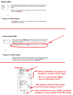
After the DDV on Rung 0007:

  • S:14 contains the unrounded (truncated) quotient
    • So if S:13/S:14 was 81009 after the MUL,
      • then S:14 will be 8100 (truncate = round down)
  • S:13 contains the remainder of the divide
    • i.e. [32-bit* S:13/S:14] modulo 10
    • To which 9 is added on Rung 0008, and the result (sum) placed in N7:72
    • So if S:13/S:14 was 80009 after the MUL,
      • then S:14 will be 9 (81009 MODULO 10)
* "32-bit" in SLC or MicroLogix 1000 is equivalent to LONG in MicroLogix 1400.


See first image below, from MicroLogix 1000 User Manual.


To duplicate that result, we could probably multiply N7:8 by 0.9, but then getting the remainder will be messy. We could also


  • Rung 0006
    • MUL N7:8 9 L9:4
  • Rung 0007
    • BST DIV L9:4 10 L9:5 <== 0.9*N7:8 rounded
    • NXB MUL L9:5 10 L9:6 <== [0.9*N7:8 rounded] * 10
    • NXB SUB L9:4 L9:6 L9:6 <== remainder (L9:4 MOD 10), or remainder-10, of DIV
    • NXB LES L9:6 0 BST ADD L9:6 10 L9:6 NXB SUB L9:5 1 L9:5 BND <== correct remainder to (L9:4 MOD 10); unround L9:5
    • BND
  • At this point, L9:5 represents S:14, L9:6 represents S:13
  • Rung 0008
    • ADD L9:5 N7:0 N7:8
  • Rung 0009
    • ADD L9:6 9 N7:72
ddv.png
 
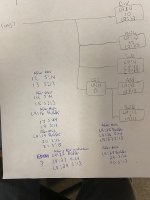
First of all thank you drbitboy for your quick responses to this thread. The pipe mill is waiting for some parts before it can startup again so I luckily have had some extra time to try to get the program to work. I have been simulating the cutoff machine by using a drill on an encoder & it appears to still have issues mainly in program file 5 which is an sti file which runs every 10ms. Drbitboy (sorry I don't know your real name) I used your example to duplicate the results of the 32bit math register but I don't know if maybe I didn't correctly understand how to put it in ladder logic. With a line speed of 60FPM N7:8 should equal 600 (rung7) but the logic I have is giving me a 60 as a result. The file was also referencing S:13 or S:14 in seven other instances in the file & I assumed (probably incorrectly) that the math register would behave the same after a DDV, MUL or DIV so I used the same ladder logic in those cases to duplicate the result. I have been programming PLC's since the AB PLC2 days but I always just accepted the -32768 to 32767 limits and I just can't get my hard head to understand the 32 bit math register used in the ML1000. Any advice would be so greatly appreciated!!! Thanks In Advance.

Duplicate Result S13S14.jpg
 

Attachments

  • User STI File 5 ML1000.pdf
    31.4 KB · Views: 4
  • User STI File 5 ML1400.pdf
    53.9 KB · Views: 3
32-bit math is essentially the same as the 16-bit math, but there are more bits:

  • signed 16-bit (i.e. INT) limits are -32768 (8000H) and +32767 (FFFFH).
    • 32768 = 2**15 = 2**(16-1)
    • 32767 = 2**15 - 1
  • signed 32-bit (i.e. LONG) limits are -2147483648 (80000000H) and +2147483647 (FFFFFFFFH).
    • 2147483648 = 2**31 = 2**(32-1)
    • 2147483647 = 2**31 - 1
The blue are the upper half of the bits (S:14), the red are the lower half of the bits (S:13), when using DDV to divide something (i.e. a 16-bit INT) into the 32-bit LONG represented by the 32-bits of the [S:14,S:/13] pair.


Brian T. Carcich
 
Last edited:
Brian,
Thanks for you help!!!
Is my ladder logic representation of what you posted on May 11th correct? I didn't quite understand the NXB LES L9:6 0 BST ADD L9:6 10 L9:6 NXB SUB L9:5 1 L9:5 BND. I'm trying to figure out why I'm missing a digit in N7:8 on rung 7 i.e. 60 vs 600. In the ML1000 program S:13 is used on rungs 25 & 28, once after a MUL instruction & once after a DIV instruction so I am assuming the result of the MUL & DIV are still going to the 32 bit math register even if the result of the operation is only a 16 bit number?
Again thanks for you prompt replies & have a good evening.
Bob Younger
 
I didn't quite understand the NXB LES L9:6 0 BST ADD L9:6 10 L9:6 NXB SUB L9:5 1 L9:5 BND.

I neglected to put comments.

The idea is to divide L9:4 by 10 [DIV L9:4 10 L9:12], and end up with the unrounded quotient in L9:12 (a la S:14 from SLC/DDV) and the remainder in L9:13 (a la S:13 from SLC/DDV).

To get the remainder, multiply the divide result, which will be an integer, by 10, and subtract the original dividend. E.g.

DIV L9:4 10 L9:12 ≡ dividend ÷ divisor = quotient e.g. 164 ÷ 10 = 16
MUL L9:12 10 L9:13 ≡ quotient x divisor = (dividend less remainder) e.g. 16 x 10 = 160
SUB L9:13 L9:4 L9:13 ≡ dividend - (dividend less remainder) = remainder e.g. 164 - 160 = 4


However, the original divide will round the quotient, not truncate it, so if the dividend is e.g. 165, the quotient is rounded up, for which the algorithm above gives us a negative remainder:

DIV L9:4 10 L9:12 ≡ dividend ÷ divisor = quotient e.g. 165 ÷ 10 = 17
MUL L9:12 10 L9:13 ≡ quotient x divisor = (dividend less remainder) e.g. 17 x 10 = 170
SUB L9:13 L9:4 L9:13 ≡ dividend - (dividend less remainder) = remainder e.g. 165 - 170 = -5


We can detect when the divide has rounded up the quotient by testing whether the remainder is less than zero, and if it has been rounded up, then to compensate

  • we add 10 to the that negative remainder, and
  • subtract 1 from the quotient
 
Is my ladder logic representation of what you posted on May 11th correct?


Yes, Rung 0006 seems to implement a non-rounding divide algorithm, so it should duplicate the SLC's DDV => [S:13,S:14].

I just realized there is a more concise and direct way to implement the algorithm:

  • BST SUB L9:4 5 L9:12 <====== Ensure DIV rounds down
  • NXB DIV L9:12 10 L9:5 <===== Divide of L9:4 that rounds quotient down
  • NXB MUL L9:12 10 L9:13 <==== Scale rounded-down quotient back to L9:4 or less
  • NXB SUB L9:4 L9:13 L9:13 <=== Calculate remainder
  • BND
 

Similar Topics

Hello i have two systems workering together with a Micrologix 1000, where their are communication between them with a serial cable. Now i have...
Replies
5
Views
2,418
Hello everyone, I'm getting to the end (I think) of migrating a program from a MicroLogix 1000 to a MicroLogix 1400. I started with my original...
Replies
10
Views
6,123
I am trying to control a Yaskawa A1000 with a MicroLogix 1400 message command. When I try to read the status I get error e0 in the message error...
Replies
1
Views
1,809
"Hello! Good day! Excuse me, I have a question regarding the 1761-NET-ENI. RSLinx has already detected it but it's not connecting to the PLC...
Replies
4
Views
134
Hi all, We have a very old pit pump system running on Micrologix 1000. Now, whenever there is an alarm for high conductivity, we want that alarm...
Replies
5
Views
1,256
Back
Top Bottom