MicroLogix 1400 - programming question

toich312

Member
Join Date
Aug 2020
Location
Vancouver
Posts
5
Hi All,

Looking for advice on programming MicroLogix 1400 with RSLogix500.

Basically, I have a client who requested I make a "simple" program that runs 5 pumps with 24 (every hour) for the day to turn on each pump at certain time for X amount of minutes. Sounds simple right?

Here is the catch based on that description:

1x setpoint for Pump 1 Step 1 Enable (on/off boolean)

1x setpoint for Pump 1 Step 1 Start Hour (example: 10:xx AM)

1x setpoint for Pump 1 Step 1 Start Minutes (example: 10:30AM)

1x Setponit for Pump 1 Step 1 Run Duration (example: 5 minutes runtime)

Total: 4x setpoints


There are 24 steps for each pump. 24*4=96 setpoints for 1 pump.

There are 5 Pumps in total 5*96= 480 setpoints

Seems like a lot of ladder logic for such simple programming and easy to make a mistake along the way. I looked into sequencer block on RSLogix500, but it is kind of confusing. Is there a simpler way to programming this?

If you can help please let me know!

Thanks in advance!
 
Are there any repeatable variables for example every pump runs for the same time or does it need to be flexible do all pumps run at that hour ? etc.
Unfortunately, the 1400 does not have AOI's (Function blocks) but there is a way round it. not exactly very small code but if you create a standard program block for a motor then call it 4 times in the main routine for example:
Have a set of variables for the motor code let's say N7:0 to N7:19
Before you call the block for the first motor move N7: 20 to N7:29 to N7:0 to 19 so in effect you pass the setpoints to temporary variables call the program block for the motor and after the call move anything that needs like setpoints etc. back to the main program. then do the same for all motors just passing the variables to bthe one program block & back.
In effect this is just like structered programing works an AOI is just a block of code that has local variables where the data for a motor is passed to the temporary variables works on them then passes out or In/Out variables back to the variables for that motor.
Not ideal but it means you only program one motor control program & call it for every motor It does save memory but still takes a bit for passing the values, however, this also happens in structured type programming
example:
Assume N7:0 to N7:19 is the data i.e. times run mins etc.
B3:0 to B3:15 is the control bits all these are used in the motor block
Block Move N7:20 to N7:29 to N7:0 to N7:19
AND B3:16 Out B3:0 (Run command) (in effet we move the actual data for that motor to the variables used in the block.

Call Motor Program
Move N7:19 to N7:29 Motor status to your program i.e. HMI
AND B3:1 OUT B3:17 Run bit for the motor output (could just use actual output if no other logic required).
Then call the block again in the same fashion for the other motors & pass the parameters to the temps used in the motor program.
Have done this on an SLC500 where we had to format the ascii chars & other control chars then send them to some displays, it saved having to write the code 16 times just pass the chars to temporary variables, call the block & do the same for all 16 displays.
I cannot show you any code as I do not have RSL500 loaded on this PC
 
Last edited:
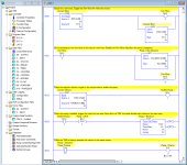
If each pump has to run every hour, can you create an integer file for each pump that is 24 elements long? Each element will represent an hour in the day (0-24) and will be populated with the minute that the pump should start (0-59). You could compare the current minute to the setpoint minute in the corresponding hour's integer file. Something similar could be done with the duration for your timers. For the current hour, MOV the setpoint from the duration N file into a timer that will control the duration of the pump. See example attached. Notice that N9 is the file for the minutes, and N10 is the file for the pump duration.

If I misunderstood what you were looking for, then I apologize.

Pump Logic.png
 
If you can help please let me know!
Sorry, but it is not yet clear to me what you are asking.

  1. What is the purpose of the boolean "setpoint?"
    1. e.g. if a boolean is 0, does that mean do not run that pump during for that setpoint?
    2. What hould each pump be doing between the specified setpoints?
  2. Are the pumps independent of each other?
  3. Do any periods from a [setpoint start time] to [a setpoint start times + duration] cross hour boundaries?
    1. Do any of those periods cross day (midnight) boundaries?
  4. Please provide an example table of two pumps' setpoints for a few hours of a day (say 00, 08, 15, 23), and then list when each pump should start and stop, assuming the pumps will not run during the other hours of a day.
    1. Please include cases where the boolean setpoint is 0, both as the first "run" of the day (in hour 00), between two runs where the boolean is 1, and as the last run of the day (in hour 23).
I am not sure of these details, but I suspect the code will look something like this:
EQU RTC[0].HR N[ipump]:[(isetpoint*5+offset_hour)] ...
... GEQ RTC[0].MIN N[ipump]:[(isetpoint*5+offset_minute)]
... LES RTC[0].MIN (N[ipump]:[(isetpoint*5+offset_minute)]+N[ipump]:[(isetpoint*5+offset_duration)]) ...
with the parenthesized values pre-calculated, or maybe converted to minute of day (0-1440).
 
@ DR: I think the OP means either a bool for enable or maybe run
If there are 24 stages & 4 per stage total 96 variables per motor
I think the best way as the 1400 cannot use FB's (AOI) is to either create 4 files i.e. NX to Nxx then either block transfer the 96 variables to say N7: call a program block that uses the N7 file do the logic return any output variables i.e. current run time & output to drive the motors etc.
Example
Block Move N10 to N7 // load the variables for Motor 1 & transfer to the motor block
Call motor function
Block move N7 to N10 //return the out parameters to drive the motor
Block Move N11 to N7 // repeat for all motors
Call Motor function
Block Move N7 to N11 // & so on
It would make sense to configure the data in two sections i.e. IN parameters to N10:0 to N10:95 (lets assume 96)
Out parameters to N10: 95 to N10:97 (used to display or control motor etc.
That way you only have one block of code for motor control called x times & only transfer the variables once per motor block call.
The only things you have to remember that any variables that need doth input & output from the block have to be transferred in & out just like an AOI or FB for example the control bits like a seal in contacts & perhaps the outputs and the actual run time time as they need to be updated in the relevant motor variable block. Have done things like this since I started programming PLC's long before they had function blocks or AOI's.
I got the idea from programming in other languages & of course Siemens who have had these since at least the 80's.
 
@ DR: I think the OP means either a bool for enable or maybe run


Yeah, that is what is confusing. If the bool is 0, then the state of the pump, both before the start time and at and after the [start time + duration], is not different than the state between those times, so why have that time at all? If a placeholder setpoint was necessary it would be simpler to use a duration that is 0 (or negative), and skip the setpoint bit; as it is, when the bit is 0, the duration is meaningless and hangs around like a stale f@rt.
 
Hey guys! First of all Thank you for response! I'm amazed by the messages, your input and time spent on responses!

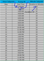
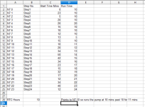
To clarify the boolean enable/disable is to enable or disable each step during the sequence. I attached an image which hopefully will explain the Control Strategy.

The idea is each pump will run independently. And each step can be either enabled/disabled for each pump.
Each pump has specific time that it will be turned on hh:mm (hh - hr setpoing, mm - minute setpoint) and also duriation in minutes approximately 5-15 min runtime every hour.

tempsnip.png
 
The RTC should handle the time in 24 hour format. 11 AM = 11, 12 PM = 12, 1 PM = 13, etc. This is why I suggested using an iNteger file with 24 elements for each pump. The number of the element can used as the scheduled hour in a compare instruction of some kind. The same can be done for the duration.

I was going to disagree with drbitboy about his bool comment, but now that I can see you are using the hour as a step, I think he is right. You don't need a separate bool to enable or disable a pump. you can set your duration to 0 and the pump just won't run for that hour. I don't know about using a negative number, passing that into a timer would fault out the processor.

Using this method requires two iNteger files per pump. The first one will be a 24 element file where the element number is equal to the hour of the day the pump is to run, and the value is the minute that the pump will turn on. The second one will be a 24 element file where the element number is equal to the hour of the day and the value is the duration that the pump will run. Another option for enable disable is to set the starting minute to anything that is not 0-59. The RTC minute variable would never be equal to anything else, thus disabling the pump for that hour.
 
Although I do not have RSL500 here is an idea, it is only a simple thing but you could pass with moves say an integer file to a scratchpad integer file then call the block for the motor control and return any parameters that need to be returned to the program so for example the start times & the run setpoints could be transferred by block move to the scratchpad file, call the motor program that uses the scratchpad file then return any parameters required i.e. actual run time & the output that drives the pump
So all the SP's would only need to be transferred before the call to the motor program but the actual run time & output to drive the motor need to be done both ways after the junp to the motor control program
So you would need to have data that only needs to be passed before the call to motor program but for the actual runtime you need to transfer before & back after the call.
So if you look I move all the data from motor 1 to the motor program variables i.e. it has a copy of the lot, the call to the motor block works on these variables, then after the block I copy the parameters that are nedded like actual run time & motor output back to the main program.
It makes sense to split the parameters to in only (transferred to the motor block) out for any parameter or variable that only needs to be read in the main program like the motor drive output, and IN/OUT parameters that are needed as an input & output to the block, may seem a bit weird but imagine the actual runtime this needs to be returned back to the motor variable so on the next scan the value is updated to allow it to be passed back to the motor block.
This way you only write one bit of code, call it many times as needed, and pass the data to & from the motor program block.
See attachment.
 
I noticed that your screenshot shows the time as hours/minutes, I know it is only a depiction of what you want, however, is it every hour i.e. motor runs sometime once every hour. it does not make sense to have start time hours for example 13:00, 12:00 i.e. mixed not in order.
The reason I ask is that if it runs every hour there will be no need to have the hours so for example if you had N7:1 to N7:24 as the minutes start time then get the hours from the RTC i.e. 13, use that as a pointer to the N7:[pointer] then just use the minutes so if the run time were 0 do not run the pump.
Just an idea you get rid of 24 registers for the hours for every pump. Also N7:24 to N7:47 become the run time so if the RTC is 10 then add 24 to this & use it as a pointer to the run time.
 
Last edited:
well he says has a client (but who knows).
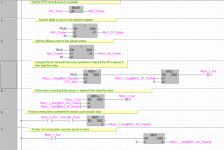
Here is some logic again not RSL but you could get the idea, in this I have assumed like I posted earlier, no need for the hours as each step is the hour so use the RTC hour to point to the relevant words.
How it works
The RTC hours are moved to a pointer, i.e. 0-23 this then points to the relevant array variable (in the case of RSL perhaps N7:0-23 this is the 24 hour steps i.e. 1 step per hour. Then the pointer has 24 added to it and stored in the Start time pointer (Point to the minute start time N7:24 -47), then 48 is added to the hour pointer to point to the run time (N7:48 - 71).
So we have 3 pointers one points to the hour for the 24 start hour one points to the start time mins & one points to the actual run time in mins.
Assume midnight (00Hrs), the first rung sets the pointer to the first step.
The second pointer points to the Start time (mins) the third pointer points to the required run time in mins.
Assume Step 1 is the first hour i.e. 00 to 01 hours the time the motor runs on step 1 is 00:10:00, the time it is to run is 20 minutes
So the logic determines the step number based on the hour, when it reaches 10 mins past midnight the motor starts, the actual time is incremented in mins & when it reaches 20 it stops the motor & resets the actual time, when the RTC incremnts to 01:00:00 it then is pointing to Step 2 & depending on the min to start & run time SP will run the motor again. & so on. you will need 4 of these one for each motor but as you can see not much logig as we are using indirect addressing.

Then step 1 is used i.e. hours = 00, as soon as it reaches 10 the motor starts, runs for the setpoint time in minutes & stops when the hour increments it moves onto step 2 & so on
So you only have 7 rungs for each motor i.e. 28 rungs in total.
It is assumed that you do not need seconds but that would not really take much extra logic per motor, one other point, it is assumed that each step would be per hour if the setpoint is at 0 the motor will not run.

Motor poll.png
 
May i suggest the following.
1. write your logic for only 1 pump and get it working. that will help you set up
your data table requirements.
2. set up your data table requirements for all the pumps.
3. create a subroutine for all the pumps.
4. save the logic for the first pump to a library.
5. import the logic into each subroutine and use edit index to change the i/o, bits, and other control bits/words.
6. go to each subroutine and do a LOCAL search / replace for the pump numbers.
you will save a ton of time by doing this. i use it a lot.
james
 

Similar Topics

Hello, I have RSLogix 500 software Version 11.00.00. I am trying to program a new Micrologix 1400 Series C (1766-L32AWA). When I open a new...
Replies
3
Views
1,712
Introduction: I'm tasked with created a rslogix program to communicate with a SCADA based PH monitoring and equalization project for our...
Replies
2
Views
1,457
Hello Everyone, I have been working on this project lately which uses the Alicat mass flow controller. The Alicat flow controller is connected to...
Replies
5
Views
2,269
Hi Group, I'm the new owner of an AB MicroLogix 1400 processor and have been trying to decide the best way to de-pressurize a compressed air tank...
Replies
8
Views
1,963
i have micro logix 1400 i need programming cable pinouts for this.....
Replies
6
Views
2,741
Back
Top Bottom