Mitsubishi FX2N-4DA Help

johnmck66

Member
Join Date
Aug 2007
Location
Manchester
Posts
96
I have the FX2N-4DA analog output module and I am trying to send a value to one of the channels to give me a 0-10v output.

Does anyone have any experience of these, using GX Developer software and PLC is a FXON-24MR-ES.

I have the 4DA manual but its so confusing, I cannot figure it out yet.

Does anyone have a simple example I can experiment with, please.
 
It is quite easy, you use the TO instruction to send the data to the Buffer memories, I currently don't have the details but will forward it as soon as I can.
But to go on:
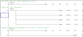
For all channels as 0-10V do a TO instruction on initial scan to buffer memory 0 i.e. BFM #0
so LD M8002 [TO K0 K0 H0000 K1] This uses M8002 (on first scan) to set all outputs to 0-10v i.e. BFM #0 so the first K0 is card slot (0) second K0 is BFM #0 H0000 sets all outputs to 0-10V (note H1000 sets ch4 to 4-20ma 3-1 0-10V
and the K1 tells the instruction to send 1 word.
To send data to all 4 channels lets assume you use memories D100 to D103 so D100 = value to channel 1, D101 value to channel 2 & so on
So the TO instruction for ending data continuously is
LD M8000 [TO K0 K1 D100 K4] This then sends the value to card 0 (first extension card) to BFM #1 the start of the analog outputs from D100-D103 K4 is the number of registers to send.
The values for 0-10v will be 0-4096 if I remember correctly. so you could scale say 0-100 to 0-4096

Analog Out.png
 
Thanks a lot, I have something I can make sense of now.


Been using Siemens for the last few years, and my memory aint what it should be these days.


Regards.
 
No problem, obviously there are quite a few parameters you can set or read in the buffer memories, like setting the sample rate (think this is only on analogue input), zero & span, type of input/output i.e. BFM # 0 the 4 nibbles are for the 4 channels so H0000 sets them all to 0-10v H0001 would set CH1 to current 0-20ma H3000 would set CH4 to 4-20ma so each hex value in the 4 nibbles can be set to the required format. BFM #1 to 4 are the values you set for the output. There are others that you can write to for adjusting the zero/span but this is a bit more complicated.
Some cards like the 4AD-PT automatically scale them for PT100 probes at -50.0 to 150.0 (Note: the actual values are -500 to 1500).
Note: for any analogue or other special cards the slot they are located (0-7) relates to the Buffer memory you write/read from. for example if the card is the first block fitted to the base unit then this is 0, for the second it is 1 etc. Digital I/O is slightly different onboard I/O is X0-X17 (assume 16 in) and a digital extension starts at X20 even though it is the first add on card.
Typical Asian way of thinking but it works and you do not have to configure the I/O addressing.
 

Similar Topics

Hi Guys, I'm looking for a bit of assistance. I'm modifying an existing machine and need to use two 4da modules, I have the first on working as...
Replies
7
Views
2,544
I've worked on one Mitsubishi PLC in the past 40 years. Now, it looks like I get to tackle another one...using GX-WORKS3-C1 software which I...
Replies
3
Views
952
I have been asked to work on a Mitsubishi Melsec FX2N-80MR PLC but have no experience with Mitsubishi at all. The hope is to get online to find...
Replies
4
Views
1,338
Hi all IÂ’ve never worked with Mitsubishi PLCÂ’s or software, but a customer at our branch has requested the PLC program for future...
Replies
0
Views
783
Hi all IÂ’ve never worked with Mitsubishi PLCÂ’s or software, but a customer at our branch has requested the PLC program for future...
Replies
8
Views
1,636
Back
Top Bottom