Mitsubishi Q-series: Adding a new Analogue Input module and how it will be recognised

Mas01

Member
Join Date
Oct 2020
Location
Leicester, England
Posts
1,109
Hi,
I'm planning to install a new Analogue Input module Q68AD-G.
It will inserted on Rack 0 Slot 4.
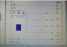
When it's installed, will the code recognise e.g. R0S4 (module ready), R0S4 (SettingRequest) and R0S4 (Setting Completed), in a similar way to the code below? (not the best screenshot, as it's from an AO module, but you get the idea). Or will they all need to be defined.
Also, I don't understand how the same register name, R0S10, can be 'commented' with three different strings. How is this possible? They look the same from the name, but they must be different things, right?


Thanks


attachment.php


Screenshot_20201216_122359.jpg
 
Last edited:
Forget the last picture...this one's better (Analogue Input).
For Info, when I double-click on R0S1 (Module Ready) on the LHS a box appears, telling me it's X10 (this happens to be the StartXY address for Rack0 Slot1). Double-clicking the next one (Setting Complete), I get X19 and double-clicking the last one (OpConSettReq) I get Y19. No idea where X19 and Y19 come from or why those values are used.

Screenshot_20211102_094832.jpg
 
UPDATE....looks like those three "R0S1" have the same Alias, hence they look the same.
QUESTION: Does anyone know why X19 to X1F have been defined/designated for Setting Complete, Offset Setting, etc.
Is this defined in the module's specification?

Screenshot_20211102_115357.jpg
 
Last edited:
Alias means nothing really, even the comment means nothing as far as the PLC is concerned, the PLC works on absolute addresses so when selecting contacts in GXDeveloper you have to use the actual address, in GXWorks this is not so, you can put a contact in a rung & use the symbol (Comment), however, the development environment knows what the actual address is so compiles it using actual address for the PLC code.
The alias is just a way of showing it is on a particular card in this instance you will notice the comment is the one that tells you which contact is, if you leave the alias out then just use the actual I/O i.e. X... & it will display the comment anyway, using the same alias is not very informative as it looks like it's the same contact used two or more times & can be confusing.

Thanks for this. Makes sense.
Any idea why addresses x19 to x1F are used?
Are they "reserved" for these specific uses?
 
Many intelligent cards have I/O points as well as buffer memories, the I/O points are if you like control signals for example X20 is the module is ready & not in fault, you can use this in your program to tell you that the channels are ok & it is valid data on the channel values, Another one is X19 when you do a setting in code (not always required if set up in parameters) this tells you that the setting of channel information is complete, there will be Yxx bits (outputs) that you tell the card to do for example Setting etc., I suggest you download the manuals & read all the information about these signals.
 
Many intelligent cards have I/O points as well as buffer memories, the I/O points are if you like control signals for example X20 is the module is ready & not in fault, you can use this in your program to tell you that the channels are ok & it is valid data on the channel values, Another one is X19 when you do a setting in code (not always required if set up in parameters) this tells you that the setting of channel information is complete, there will be Yxx bits (outputs) that you tell the card to do for example Setting etc., I suggest you download the manuals & read all the information about these signals.

Many thanks again. Will do.
 

Similar Topics

I need to add a QX10 module to our PLC because we've run out of DI channels. Does this module need to be configured in a similar way to the...
Replies
7
Views
2,217
I want to add a new ANALOGUE INPUT module into our PLC (Q68AD-G), but I'm a bit confused about something. I would've thought that the IO...
Replies
30
Views
18,526
We recently ran out of spare AD channels on our PLC and now I've just received a new Q68AD-G to give us extra capacity. My plan: 1. remove one of...
Replies
21
Views
6,301
Hi, I've run out of analogue input channels on my Q68AD-G module. If I add a new Q68AD-G module and install it into a spare (blanked-off) slot, it...
Replies
2
Views
1,335
how to communicate FactoryTalk Optix and Mitsubishi Q Series. I want to know the details of that
Replies
0
Views
37
Back
Top Bottom