You are using an out of date browser. It may not display this or other websites correctly.
You should upgrade or use an alternative browser.
You should upgrade or use an alternative browser.
Mitsubishi Q series: Averaging value before displaying on HMI
- Thread starter Mas01
- Start date
drbitboy
Lifetime Supporting Member
DR your code does not work, a constant float has to be E 0.1 corrected that this is the result
nice catch, I updated that post to be [E/P D420 E10 D472]
It's often a bit beyond me to do this stuff in my head.
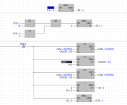
Also, of we are going to use indirect, why bother shifting the data? wouldn't it be better to
-+-[< Z0 K0 ]-+-[MOVP K0 Z0]

 +-[> Z0 K19]-+


SM412

-] [-+-[E-P D444 D424Z0 D444]

     +-[E/P D420 E10 D424Z0]

     +-[E+P D444 D424Z0 D444]

     +-[+P Z0 K2 Z0]
You have to be careful using the index registers "Z" in scan, they are used by other functions or if used elsewhere, the way to do it once per scan then save it to a register then restore it before use if that is the requirement, however, if in a for/next it just jumps back until the number of iterations have been completed. Not that it matters but just use the "P" function on the SM412 it saves a little processing rather than the P function version of all the shifts etc.
drbitboy
Lifetime Supporting Member
You have to be careful using the index registers "Z" in scan, they are used by other functions or if used elsewhere, the way to do it once per scan then save it to a register then restore it before use if that is the requirement, however, if in a for/next it just jumps back until the number of iterations have been completed. Not that it matters but just use the "P" function on the SM412 it saves a little processing rather than the P function version of all the shifts etc.
Good points! thanks.
drbitboy
Lifetime Supporting Member
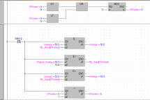
This is why I like the GXWorks2 or 3, as it's IEC compliant you can use arrays & no need for Z register just a variable makes things a little clearer.
It does actually use the Z pointer registers but that is in the compiled code so you do not have to worry about them.
Sweet!
One (minor?) inconvenience with the incremental approach I proposed is that there needs to be additional code to initialize the array elements and the average to zeros (or to the current value); that is not a problem when the code re-calculates the average from scratch from the entire array at least every every time a new value is added.
It's not a problem from initial start, all the registers are initialised, the array is actually D addresses so for example a float array[0..9] is say D400- D419
so 20 addresses, these (if set in project) are retentive, if PLC is powered down then back up they keep the data, so yes for 1 second it will retain the last average then after 10 seconds will be a true average, assume the machine is stopped i.e. no pressure, then it will decay to 0, same with starting as the pressure rises so will the average, but again it will take 10 seconds to stabilise, but then again so will the actual pressure as it ramps up.
The only problem is that every second the average pressure will jump + or - rather than every scan, but the averaging process will tend to smooth it out reasonably assuming the pressure (or what ever it is) is displayed on the HMI as ###.# so only 0.1 resolution, if the jump in values is +/- 1.0 or more then it will still display varying data every second.
What Mas can also do is on the HMI, set the decimal places to say 1 (assuming this is accurate enough), also set the sampling rate this will slow down any change on that tag as on the HMI it is only a display & no script.
If his analogue value is changing that rapidly & by a large amount then there must be something wrong.
Ah.. I noticed the analogue is flow rate, no idea how this is controlled so it does appear to be rather bad control, perhaps he could post some information on how the flow rate is controlled, what resolution does he need etc.
Last edited:
Mas01
Member
The sensor is a differential pressure sensor.It's not a problem from initial start, all the registers are initialised, the array is actually D addresses so for example a float array[0..9] is say D400- D419
so 20 addresses, these (if set in project) are retentive, if PLC is powered down then back up they keep the data, so yes for 1 second it will retain the last average then after 10 seconds will be a true average, assume the machine is stopped i.e. no pressure, then it will decay to 0, same with starting as the pressure rises so will the average, but again it will take 10 seconds to stabilise, but then again so will the actual pressure as it ramps up.
The only problem is that every second the average pressure will jump + or - rather than every scan, but the averaging process will tend to smooth it out reasonably assuming the pressure (or what ever it is) is displayed on the HMI as ###.# so only 0.1 resolution, if the jump in values is +/- 1.0 or more then it will still display varying data every second.
What Mas can also do is on the HMI, set the decimal places to say 1 (assuming this is accurate enough), also set the sampling rate this will slow down any change on that tag as on the HMI it is only a display & no script.
If his analogue value is changing that rapidly & by a large amount then there must be something wrong.
Ah.. I noticed the analogue is flow rate, no idea how this is controlled so it does appear to be rather bad control, perhaps he could post some information on how the flow rate is controlled, what resolution does he need etc.
I was given an equation to convert that dP to flow in litres/sec. The calculation is accurate and, for a given dP, the PLC-calculated flow rates match those on the engineer's spreadsheet.
When the rig is running, the flow rate doesn't vary that much, but the vertical bar is jittery and difficult for the operator to focus on one value and write it down on his checklist.
I guess ultimately, the "fix" could be done in the HMI by slowing down the display rate (although I've not seen a 'sampling rate for display' feature in the HMI, GT Designer3).
I will implement the 'average' code and report back.
Many thanks.
Last edited:
Mas01
Member
Mas01
Member
drbitboy
Lifetime Supporting Member
should D630 have the same value as D420? For some reason D630 always shows 0.
See this link for that reason.
TL;DR
The [SFTLW D630 K22 K2] shifts the 20 words (10 floats) starting at D630 "up" to the 20 words starting at D632, and loads 0s into the lower (non-overlapped) two words. So that 0 in D630 is expected.
D632 <= D630 "+ K2"
20 words shifted <= "K22" - "K2"
Mas01
Member
See this link for that reason.
TL;DR
The [SFTLW D630 K22 K2] shifts the 20 words (10 floats) starting at D630 "up" to the 20 words starting at D632, and loads 0s into the lower (non-overlapped) two words. So that 0 in D630 is expected.
D632 <= D630 "+ K2"
20 words shifted <= "K22" - "K2"
I think I get you. Cheers Drbitboy.
So it's like once the shifting is done, D630 is "back-filled" with zeros...well, that's how I like to I think of it.
drbitboy
Lifetime Supporting Member
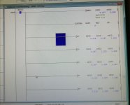
I see the displayed running total is 2.09...; for the 10 floats from D632 to D650 shown in that post I get a sum of 2.02... This is not necessarily an issue, as it could be an effect of the temporal sampling of the data displayed in that window, but worth investigating perhaps.Extra picture added to show monitored "live" values.
D652 is the totaliser.
D654 holds the average.
Quick estimate/check
3 values ~0.236 (.2 + .036); 4 values ~.204 (2 + .004); 3 values ~.1666 (.2 - .1/3); 10 values total. So the excess relative to .2 is
- 3*(.036+.004) + .004 - 3*(.1/3)
- = 3*.040 + 0.004 - .1
- = .120 + .04 - .1
- = 0.024
Similar Topics
how to communicate FactoryTalk Optix and Mitsubishi Q Series. I want to know the details of that
- Replies
- 0
- Views
- 37
HOW to communicate with OPTIX and Mitsubishi's Q Series PLC?? PLEASE HELP ME
- Replies
- 0
- Views
- 47
In this sample programming, what does U4 mean?
Any assistance would be greatly appreciated.
- Replies
- 8
- Views
- 274
Hi,
I have a project with a R04CPU, RD77GF16 and a RJ71PN92 modules. The cell is given to me to change the program since the previous integrator...
- Replies
- 9
- Views
- 290
Hi
One of the PLC's that I maintain/update is a Mitsubishi Q-Series, probably installed about 10 years ago.
At the moment, ALL the wires from...
- Replies
- 13
- Views
- 1,172


