Mitsubishi Q series: configuring an IO channel

Mas01

Member
Join Date
Oct 2020
Location
Leicester, England
Posts
1,109
Hi, this code refers to a Mitsubishi Q68AD-G card.
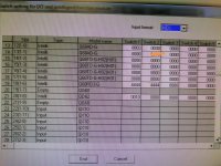
Ch 06 was previously a SPARE channel, but I want to use it as a 0-5vDC input (D33). To this end, I updated the I/O assignment (switch 2) from the default 0000h to 0030h, as per the module spec. I then wrote to the PLC. Then I put 0.5Vdc onto that channel, but the value stayed at zero. Anyone know why? E.g. do I need to do more configuring of that channel in GX developer? Thanks

IMG_20201202_170303.jpg IMG_20201202_171116.jpg
 
Last edited:
First of all have you downloaded the parameters to the PLC as it needs this to set the card properties (you will probably need to re-boot the PLC as well).
Also I noticed that G10.0 -7 are not on so no data will be transferred until the rung is true, off hand I don't know what those bits are but I suspect these are channel enabled bits or conversion done bits I will need to have a look.
Also is this a new card or an existing one that has some channels already in use.
Thanks for the reply. My responses below:

When I downloaded to the PLC, I put a tick in all the available tickboxes (main, analogues, I think Device parameters was also a tick option?).

I have NOT rebooted the PLC, but I know there's a circuit breaker for that. So will do that tomorrow.

As for G10.0 -7, they are "conversion complete bits". I would expect those to be set true but they aren't.

Yes this is an existing card with some channels already in use.
 
I believe somewhere above the posted code there should be a bit of a program where it is done on a one shot i.e. on start up of PLC it sets certain bits in the Y area of the card and then reset the trigger (or set this is because some programmers use a not ) as the one shot then set it so it only does it's job in one scan i.e. set the card configuration, mode, etc. I would now check if the other channels are working because it does not look like it.
If they are have you connected the source i.e. 0-5v to the correct connectors.
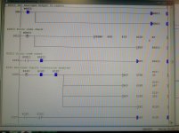
These are the rungs above the ones I posted earlier. No idea why those hex values.are.being used,.or if I need to change them to make ch 6 readable.

IMG_20201203_094525.jpg
 
There is some very funny logic there, In ladders 1049 & 1087 R1S0 is used as N/0 & N/C so will never be true.
It is almost as if these have been disabled ?. So R1S0 bit will never be true. as you can see in the status that it is off so will not transfer the data. However, in the previous post it shows R1S0 as being on for the transfer of data to the D registers ? but by the look of it as this logic will not set the conversion enabled bits how can it convert ? This seems very weird.
Also I don't know why but R1S0 does not seem to be a symbol but a real address, however, I cannot enter this as it says it's an error I have no Idea why you can have this as a contact normally contacts can only be X Y M & Dx.x
When I type this in it says non usable type. The only thing I can think of is this may be a conversion from A to Q series PLC and although R1S0 may be valid when it converted it it allows it but you could probably not add it in a Q series. I'm clutching at straws here as I do not have an A series & try to convert it. The normal way is to use X & Y bits of the card see pic.
I would normally suggest putting a pulse contact across the ladder that enables the conversion to bypass the logic so that it did a one shot to trigger the [MOV H0FE U10\G0 ] But a change in this logic may not re-compile so I would not do it on a live system. I will see if I can find out how the address R1S0 can be used but at the moment I have no idea.
Is the system working after the change because looking at the status there is no analogue values.

Init.png
 
For info, here's the next bit of code... another Q68AD-G (AI module). For this one, though, some live values are visible. So how can they be live when the same NO/NC conflict is there? I'm lost.

IMG_20201203_111043.jpg
 
Might be wrong....got a feeling I need to change the statement on rung 1049...at the moment it says H0FE. This means only the first channel is enabled for A/D conversion, according to the Q68AD-G manual, section 3.4.2. This ties in with the card, which only has the first channel used (but now also I want another channel to work too).
 
I think you are right, according to the data sent (OFE) means channel 1 is 0 and all other channels are 1 and as 0 = Enable & 1 = Disable I think you need to set it to 6E I think 1101110 so it will enable channels 1 & 5.
It seems weird that the BFM bits 10.0 - 7 are not shown as on but are working my only assumption is that these are switching too fast for the coms on monitor to see them.
 
You will probably have to re-boot if you do an on-line change to the enable value or if total download then it will put it into stop and then set it to run should re-config the enables (not sure how that is doing it as it looks like the N/O & N/C contacts of R1S0 would not allow the config, however, not knowing how they work in that mode it might be ok, it's just very confusing as conventional logic goes from left to right but not being able to re-create without the hardware I'm not sure.
 
I think you are right, according to the data sent (OFE) means channel 1 is 0 and all other channels are 1 and as 0 = Enable & 1 = Disable I think you need to set it to 6E I think 1101110 so it will enable channels 1 & 5.
It seems weird that the BFM bits 10.0 - 7 are not shown as on but are working my only assumption is that these are switching too fast for the coms on monitor to see them.
Well, that seemed to fix it.
D33 seems to be responding to changes in VDC. I've learnt something today!
 
It's very interesting how those R1S0 bits are in the program as I cannot replicate it it will not compile and the N/C & N/O in series contacts in normal logic would never be true I have used the same contacts to disable a rung to test things so I really don't know what is going on there but it must work as changing the enable bits seems to have cured your problem, so it seems I have learnt something although I would never use it I would set the card using the GX Configurator-AD to do it that way you don't need any code in the PLC, anyway glad it's sorted.
 

Similar Topics

I've got a Q68AD-G (Mitsubishi A/D card) and I'm trying to set up channel 6 as a 0-5V range. I've changed the SWITCH SETTINGS so that CH6 says...
Replies
2
Views
1,530
Hi, I've got a Q68AD-G card (8 channel). I want to configure it for 0-10v analogue input. I've enabled the channel by using Un\G0. Then I used the...
Replies
4
Views
1,832
Hi, I need to send a digital output to turn a water pump Inverter driver ON/OFF. To this end, I'm planning to use a Digital Output Module, i.e. it...
Replies
16
Views
3,540
how to communicate FactoryTalk Optix and Mitsubishi Q Series. I want to know the details of that
Replies
0
Views
37
Back
Top Bottom