Mitsubishi Q series , configuring a PLC digital output

Mas01

Member
Join Date
Oct 2020
Location
Leicester, England
Posts
1,109
Hi, I need to send a digital output to turn a water pump Inverter driver ON/OFF. To this end, I'm planning to use a Digital Output Module, i.e. it outputs a Y-value. It has 8 channels, but unlike the analogue modules, there doesn't seem to be any place in the code to configure/set-up the channels. I mean, if you look down the LHS of GX developer, you can see various things like ANALOGUE, DEFAULTS, MAIN but nothing for 'digital'. When I was configuring analogues, I had to change buffer UnGn values to get the PLC to recognise the channel, but there's nothing similar for digitals. Thanks
 
Last edited:
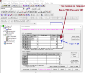
The module does not "output a Y value". The module turns an output on or off. The Y values are the memory addresses of the module's individual output points. If the starting address of the module is Y0010, the first point of the module is Y0010, the second Y0011, the third Y0012, etc.
 
The module does not "output a Y value". The module turns an output on or off. The Y values are the memory addresses of the module's individual output points. If the starting address of the module is Y0010, the first point of the module is Y0010, the second Y0011, the third Y0012, etc.

Thanks for the correction.
My point is, though, do the channels of the digital output module need to be configured in a similar fashion to the analogue module?
 
My point is, though, do the channels of the digital output module need to be configured in a similar fashion to the analogue module?
There isn't anything on a discrete output module that needs configuring other than to assign an address to it which is done automatically.
Disclaimer: I have only ever done one Mitsubishi project. That was four years ago and I've forgotten most of what I learned in the process of doing it. Parky, or someone else more knowledgeable than I will correct me if I'm wrong.
Cheers for the information, Steve.
Maybe you're right about what you say. The module is an existing one in the PLC (and already configured). Thanks
 
Mas01: The only configuration on a Q series for Digital I/O cards is to set the type of module in the PLC Parameters, if this is an existing module then it will already be configured so all you need to do is write the conditions to control the output like
Y23
-----| |-----------------( )

So the instruction is OUT Yxx

Brilliant, glad.to hear it.
 
Hi. I only have experience with old Melsec Q PLC and the old GX Programmer or GXWorks 2. I did not know the digital modules can be recognised automatically as suggested above. Anyways, I have always configure the digital IO in the program. An example is below. It is not a real program.

2020-12-15_Melsec.png
 
Last edited:
Hi. I only have experience with old Melsec Q PLC and the old GX Programmer or GXWorks 2. I did not know the digital modules can be recognised automatically as suggested above. Anyways, I have always configure the digital IO in the program. An example is below. It is not a real program.

Cheers for this. Yes, my QY18A module is already configured and the start/end address has similarly been defined. Thanks
 
Hi, I need to send a digital output to turn a water pump Inverter driver ON/OFF. To this end, I'm planning to use a Digital Output Module, i.e. it outputs a Y-value. It has 8 channels, but unlike the analogue modules, there doesn't seem to be any place in the code to configure/set-up the channels. I mean, if you look down the LHS of GX developer, you can see various things like ANALOGUE, DEFAULTS, MAIN but nothing for 'digital'. When I was configuring analogues, I had to change buffer UnGn values to get the PLC to recognise the channel, but there's nothing similar for digitals. Thanks

When all this travel restriction and social distancing is done with can i suggest you get in touch with the excellent guys at LC Automation up in Blackburn and book yourself on a Mitsi Q and FX introduction training course, they are two days a piece and only cost £475.

https://www.lcautomation.com/Page/Training.aspx
 
Alfredo: I didn't actually say that it auto configured I know that in Mas01's case he has an existing card so it would already be configured, but in saying that I believe if you install normal I/O and read the PLC Parameter It might have the card types, however I have never actually done it even though I have done many Q series I normally configure in the the PLC parameters first I must try it sometime.
Edit: Come to think of it I had a unit but no battery, I powered it up & it went into fault, I reset it and read the PLC Parameters and the card was there so it may be possible, however, on intelligent cards it will probably default to standard mode.
 
Last edited:
Alfredo: I didn't actually say that it auto configured I know that in Mas01's case he has an existing card so it would already be configured, but in saying that I believe if you install normal I/O and read the PLC Parameter It might have the card types, however I have never actually done it even though I have done many Q series I normally configure in the the PLC parameters first I must try it sometime.
Edit: Come to think of it I had a unit but no battery, I powered it up & it went into fault, I reset it and read the PLC Parameters and the card was there so it may be possible, however, on intelligent cards it will probably default to standard mode.

Correct, in my case, it's already cofigured with a start/end address.
 
Alfredo: I didn't actually say that it auto configured I know that in Mas01's case he has an existing card so it would already be configured, but in saying that I believe if you install normal I/O and read the PLC Parameter It might have the card types, however I have never actually done it even though I have done many Q series I normally configure in the the PLC parameters first I must try it sometime.
Edit: Come to think of it I had a unit but no battery, I powered it up & it went into fault, I reset it and read the PLC Parameters and the card was there so it may be possible, however, on intelligent cards it will probably default to standard mode.
I think you are right. I just have never done this and personally would prefer to configure the modules in the GX Developer program.
 

Similar Topics

I've got a Q68AD-G (Mitsubishi A/D card) and I'm trying to set up channel 6 as a 0-5V range. I've changed the SWITCH SETTINGS so that CH6 says...
Replies
2
Views
1,530
Hi, I've got a Q68AD-G card (8 channel). I want to configure it for 0-10v analogue input. I've enabled the channel by using Un\G0. Then I used the...
Replies
4
Views
1,831
Hi, this code refers to a Mitsubishi Q68AD-G card. Ch 06 was previously a SPARE channel, but I want to use it as a 0-5vDC input (D33). To this...
Replies
11
Views
2,557
how to communicate FactoryTalk Optix and Mitsubishi Q Series. I want to know the details of that
Replies
0
Views
37
Back
Top Bottom