You are using an out of date browser. It may not display this or other websites correctly.
You should upgrade or use an alternative browser.
You should upgrade or use an alternative browser.
motion control with profidrive
- Thread starter adam_lhadi
- Start date
kamenges
Member
You say you are not getting a good result when positioning. What about the result is not good. What is the actual issue?
Keith
Keith
adam_lhadi
Member
OP
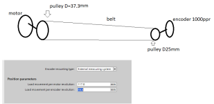
when i aske for a 100mm displacement i get 23mm even in low speed
adam_lhadi
Member
OP
You say you are not getting a good result when positioning. What about the result is not good. What is the actual issue?
Keith
when i aske for a 100mm displacement i get 23mm even in low speed
adam_lhadi
Member
OP
If your drawing is accurate, then your ratios don't match. 117mm would yield 78.4, not 78.5. You're accumulating .1mm of error per revolution.
when i aske for a 100mm displacement i get 23mm even in low speed
adam_lhadi
Member
OP
Steve Bailey
Lifetime Supporting Member + Moderator
23 mm movement for a 100 mm command sounds like a combination of quadrature configuration and the arithmetic errors that robertmee pointed out. If you're using an A quad B encoder you're getting 4000 lines per revolution, not 1000.
Neither 37.3 mm nor 25 mm represent an integer number of teeth for appears to be an 8mm pitch. To get the most accurate ratio, instead of measuring the diameter of the pulleys, count the teeth and multiply by the pitch to get the distance traveled per revolution.
Neither 37.3 mm nor 25 mm represent an integer number of teeth for appears to be an 8mm pitch. To get the most accurate ratio, instead of measuring the diameter of the pulleys, count the teeth and multiply by the pitch to get the distance traveled per revolution.
Last edited:
23 mm movement for a 100 mm command sounds like a combination of quadrature configuration and the arithmetic errors that robertmee pointed out. If you're using an A quad B encoder you're getting 4000 lines per revolution, not 1000.
Neither 37.3 mm nor 25 mm represent an integer number of teeth for appears to be an 8mm pitch. To get the most accurate ratio, instead of measuring the diameter of the pulleys, count the teeth and multiply by the pitch to get the distance traveled per revolution.
I'm with steve. Correct the gear ratio as I pointed out earlier, and set your encoder counts to 4x
adam_lhadi
Member
OP
I'm with steve. Correct the gear ratio as I pointed out earlier, and set your encoder counts to 4x
i don't have an explanation to this but under basic parameters /encoder i changed A/B count fourfold to A/B count then t works well
i returned to A/B fourfold also worked well
Rob...
Lifetime Supporting Member
For a system like this where I presume it's just for testing/learning how to set up the software.
I'd ask to move x mm, measure what it actually moved. Then just calculate backwards.
I'd ask to move x mm, measure what it actually moved. Then just calculate backwards.
i don't have an explanation to this but under basic parameters /encoder i changed A/B count fourfold to A/B count then t works well
i returned to A/B fourfold also worked well
many of the TO parameters have 3 different places the value is stored: in the offline project, in the start value of the TO DB in the PLC, and the actual value in the PLC. If you don't take this into account as you do testing, you can very easily get situations where you make changes that have no effect now, but maybe do later on.
I could very easily see that explaining what you said above, where it didn't work, and then it did work, but then it kept working once you changed the setting back. Something to keep in mind.
Similar Topics
I have always controlled servos in Rockwell motion using position loop. I have an application where one process will push against a servo...
- Replies
- 3
- Views
- 274
How do I adjust motion control parameters using Logix Designer?
Such as:
motion axis stop
I will make an adjustment like changing the...
- Replies
- 1
- Views
- 323
Hey guys,
On my system, i got prop valve controling cylinder on the left and right to adjust the center of a lumber before it get in a woodmill...
- Replies
- 8
- Views
- 935
Hi, I have an application that currently utilizes SEW drives and programming that we are attempting to convert to Allen Bradley CompactLogix and...
- Replies
- 9
- Views
- 1,147
Hello.
We have a Powerflex 700s phase II firmware 4.002, but the encoder card is burned. We want to disable it to use the Drive without motion...
- Replies
- 0
- Views
- 458


