Motorized Pot

I thought the speed reference on most drives was daisy-chainable. Using a motorized pot seems to be a very...Rube Goldberg-ish way of handling it. Kind of makes me wonder where the marble rolls down a chute which somehow inflates a balloon and then shoots a gun at something.
 
With an MOP, line speed can be adjusted from any point on the line.
Rd, please enlighten me about MOPs. When you have several MOPS controlling the same speed, how do you wire them, and how do you keep each MOP setting from interfering with the settings of the other MOPS? In other words, if you were using actual potentiometers, and wired several in series or parallel, each would affect the others, unless you also had a switch that controlled which pot had control at any particular time. What is the secret sauce that allows using several MOPs at once?
 
Last edited:
I'm trying to control main drive speed adjustment from multiple locations on a production line. The Main station needs to be updated with any other location changes. I was thinking of using a motorized pot, but can't find what i'm looking for. Has anyone had success with a certain brand motorized pot or have any ideas on how to do same function?
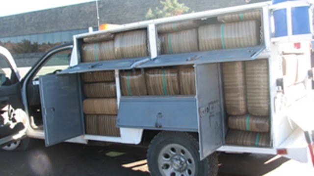
Are we sure that he isn't looking for this?

18720639_BG1.jpg

Truck load of pot.
 
Rd, please enlighten me about MOPs. When you have several MOPS controlling the same speed, how do you wire them, and how do you keep each MOP setting from interfering with the settings of the other MOPS? In other words, if you were using actual potentiometers, and wired several in series or parallel, each would affect the others, unless you also had a switch that controlled which pot had control at any particular time. What is the secret sauce that allows using several MOPs at once?
Since he said "The Main station needs to be updated with any other location changes", I am guessing that he want to mount a single MOP at the main station. The remote controls will simply drive this pot up and down, similar to using 'increase/decrease' digital inputs on a VFD.

It may be easier to use the MOP function built into most drives, and display the current setpoint on an HMI, but perhaps his existing drive doesn't have this option, and/or there is no HMI... :confused:

🍻

-Eric
 
Rd, please enlighten me about MOPs. When you have several MOPS controlling the same speed, how do you wire them, and how do you keep each MOP setting from interfering with the settings of the other MOPS? In other words, if you were using actual potentiometers, and wired several in series or parallel, each would affect the others, unless you also had a switch that controlled which pot had control at any particular time. What is the secret sauce that allows using several MOPs at once?

???
You only have ONE MOP controlling a device. The MOP however, can take any number of increase/decrease inputs, as they are only pushbuttons.

Another option, if you must use actual potentiometers at each location (and this works surprisingly well actually) is to feed each pot into a PLC, and then select the current 'Active' pot depending on which one was last changed. An operator can walk up to any one on a line, give it a wiggle, and have control from that point. The most recently used one then feeds a single analog output. For this method, I only use single turn pots.
 
Maybe a little extra explanation would help. Years ago a speed potentiometer for a variable speed drive system (usually DC) would actually be a large high-wattage wirewound potentiometer with a servo motor mounted on it to move the wiper across the control surface. The operator would have two push buttons, one to run the servo motor one way to increase the speed setting and the other to run the motor the other way to decrease the speed setting. This is where MOP or Motor Operated Potentiometer got its name.

Today, while the name still appears, there is no large pot or servo motor. The name refers simply to a form of speed control where there is no analog input but rather two digital inputs. One is an "increase speed" input and the other is a "decrease speed" input.

There are several benefits to using this kind of speed control. First, if the speed input to a modern drive is to be controlled with signals from a PLC, you don't have to buy an analog card for the PLC. You set up one digital or relay output as increase and a second digital or relay output as decrease speed. Second, an analog speed pot must be located in only one place but, with MOP, you can wire as many Increase pushbuttons in parallel as needed and the same for multiple Decrease pushbuttons. Thus, you can get full and equal speed control from multiple operator stations. Third, MOP is far less noise sensitive than analog control.

Most AC and DC drives today offer this kind of speed control. It is not always called MOP but it usually is there somewhere.

I understand that some PLC's also can simulate this same kind of Increase/Decrease control. It may be called MOP, Floating Point, or some other clever name but they all pretty much work the same way.

Hope this helps
 
Thanks, guys. I get it now. Really you only have the equivalent of one MOP, but many control points that can drive that MOP up or down. It makes sense now.
 

Similar Topics

Can any one suggest, I have Motorized valve Gas Burner (open and close) i want to control with PLC PID Control with RTD input and close and open...
Replies
12
Views
5,963
I'm working on a system with a motorized ball valve. It's a basic 120v unit with built-in limit switches and two inputs... one opens and one...
Replies
3
Views
2,986
Ready to give up and build something in-house...🔨 Been googling for a couple of days now and the only positive return was some Austrian...
Replies
5
Views
1,439
I am attempting to set up my zones according to the literature that came with the MDR. Is there some rule of thumb for setting up zones (zone...
Replies
1
Views
1,285
I am connecting a Motorized control valve to a PLC5 with a duty cycle of 50%ED. Now duty cycle as I know it to be is the ratio of time on and...
Replies
6
Views
4,656
Back
Top Bottom