OT: I really need to ask - Electrical question

theripley

Member
Join Date
Jul 2008
Location
laguna
Posts
545
Hi,

I am very confused this time, there is no other way but to consult. This is out of topic, but please spare me.

I am currently troubleshooting a fire alarm system that I suspect is having a ground fault (sigh). I am researching on how to check which lead/ conductor is faulty. I have read on one article that I need to take out all wiring from the electronic panel & bring out my ohmmeter, set it to the highest continuity & start reading between each lead/ conductor vs. a given ground. Considering correct electrical practice have been made during installation, it is safe to consider the electrical conduit as a ground.

Here's where I am very much confused. I have known that as a "good" electrical practice, say for a single phase installation, the neutral line must be connected to a ground (see attached page). When a fault appears, it will not harm any component or human in any instances, it will simply blow the fuse or trip the breaker. Given this statement, if I follow what the article above suggests, then I will surely read multiple continuity to ground.

I am really confused please help me.

1-0001.jpg
 
Yes, the neutral is connected to ground, but ONLY at the main circuit breaker panel. This is why the neutral is also called the 'groundED' conductor (not to be confused with the groundING conductor, i.e. ground wire). Therefore, you would expect to read continuity from the neutral to ground.

🍻

-Eric


What exactly is the difference of a groundED & groundING conductor? Aren't they bought connected to the same ground?


Thanks for the link.

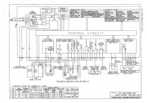
I have attached the wiring diagram by the fire alarm maker. I would assume that with this connection, it will be P2 which will have continuity to ground E. In that case conductor PLC to HH + will no way be connected to the ground E. Whichever will be connected, however, is the faulty line.

FYI, the trouble I am encountering is with regards to FPL (fuse). The user informed us that it was once blown by unknown reason. They intend to replace it, but when they tried, all buzzers in 1 of their zones started buzzing. They took it out & never returned. Amazingly though, even without the FPL fuse fire alarm still works, at least for the rest of the zones (they have 5 zones).

That's why I am considering ground fault since there has been new sensors installed in their building. I suspect there were wiring trouble upon the addition.

If you could share other troubleshooting tips, please do so. I will greatly appreciate.

2-0001.jpg
 
Try to establish if the fault is on the supply, sounder or sensor circuit. I seems as though it is on the detector side of things.

I don't know your local standards but most modern fire alarm panels have "End of line" units so that the detector circuits can be monitored for short and open circuits.

Does the panel itself have a fault or fault code displayed?
 
Does the panel itself have a fault or fault code displayed?


There were no display on the anunciator, whatsoever, when fuse FPL is not connected. When fuse FPL is connected, there was no display either, only buzzing of the local sounders on 1 of the zones. I read the resistance by ohmmeter on each detector line, all are 10 k-ohms (as indicated on the panel) except for 1 zone, the one which local sounders are buzzing when FPL is connected. That zone reads only 4 k-ohms. I am trying to find the EOLR location on this zone, in which initially I could not find elsewhere. It keeps me wondering where is that 4 k-ohms coming from.

I tried simulating an open circuit as well on each zone by removing 1 sensor on each loop. Open circuit alarm is evident on 4 zones but not on 1 zone, the same zone I am having trouble. It did not detect the open circuit I was simulating. Funny thing is when I simulate an alarm on 1 of its smoke detector (by smoke simulation), alarm was evidently detected.

This is such a headache. Please help.
 
Last edited:
Theripley - Yes, the eol value is 10K ohms so ctearly there is a fault on that zone.

Unfortunately, it looks like you will have to fault find the "Old fashioned" way by moving the eol resistor to the first detection point on the zone and disconnecting the outgoing circuits to see if it clears.

If there are many detectors/call points, start in the middle to save time.

Finally, what wiring system is used, conduit, mineral insulated, FP cable? on a detector/call point circuit there should be NO reading between the detector wiring and earth (Ground).

If you are really unsure - because you are really a plc guy, this actually sounds like a problem for the electrical company who added the new circuits.
 
If you are really unsure - because you are really a plc guy, this actually sounds like a problem for the electrical company who added the new circuits.

I'm a plc girl:)


Finally, what wiring system is used, conduit, mineral insulated, FP cable? on a detector/call point circuit there should be NO reading between the detector wiring and earth (Ground).

I am not sure about the insulation, but I think for the wire they use TF & it is enclosed in metal conduit.

One thing bothers me though, I tried disconnecting the 5th zone (troubled zone) by disconnecting its wire & replacing it with a 10 k-ohms resistance then I tried putting the FPL fuse back, the sounders still buzzed.

My conclusion is that aside from my 4 k-ohm problem, there are other problems lying. It looks like the problem causing the sounder buzzing is independent from the eol problem on zone 5.

What do you think?
 
Very sorry PLC GIRL!

I looked more closely at the FPL fuse and it is labelled "led/plc". Is this connected to an external device and if so, what is it indicating?

It looks like it indicates "Supply healthy" but only has a 0.63a capacity. If this causes the sounder buzzing, make sure there is not a fault on this circuit or it is not overloaded.
 
I tried disconnecting the 5th zone (troubled zone) by disconnecting its wire & replacing it with a 10 k-ohms resistance then I tried putting the FPL fuse back, the sounders still buzzed.
It looks like the problem causing the sounder buzzing is independent from the eol problem on zone 5.

What do you think?

On the units i have worked with, the detectors work somewhat like 4 to 20 loop powered sensors. The control station needs to have the whole detector in the circuit not just the resistor. To rule out the wiring pull one detector from a known good working zone and wire it up to the defective zone (do not use any of your suspect wiring) near the cabinet. By doing this you can find out if it's a detector or wiring.
 
If zones 1,2,3,4 are reading 10k ohms on the wiring out from the panel, and your drawing shows it should be, as that is the value of the End of Line Resistor ( EOL ) shown, then the fire monitoring system says all is well, you have no fire and no defects,

This will also be the case if there is several Manual call points on the same zone, but in this case there will be only ONE EOLR and it should be at the furthest point in the wiring away from the Fire panel, and in the fire system I have worked on all those call point switches were in series.

Now if zone 5 shows a reading of 4K ohms, this would indicate to the fire panel that the wiring is not shorted and its not open, but it is not showing a correct value so is probably in a state that show no fire but also no defect.

Wild Guess now
It may have fallen into the setting I was told was a NO Fire Monitoring signal and it may be set up to cause the sounders to buzz but not call the fire brigade.

Now to get 4k ohms on your system my guesses are
1 . the one EOLR has been made a 4K ohm resistor instead of 10k ohms
2 . they added 1 or probably 2 new manual call points, and wired then from the switch that had the EOLR in it, and just copied what they saw, adding additional EORL onto the system.
3 . one of the switches is in fire position but has a high resistance ( 6 K ohm ) on that switch contact, I'm thinking as a 10 K and 6 k in parallel would give 4k ohms

Now if I was fault finding on this system,
I would look for 2 new switches that were installed and check for and EOLR in each of them then find where they connect to the original switch wiring and look for what was the old EOLR
If they used !2k Ohms resistors 3 times you would get 4k ohms.

Quote:
Originally Posted by markie

If you are really unsure - because you are really a plc guy, this actually sounds like a problem for the electrical company who added the new circuits.

I'm a plc girl

Hi there Erica
Well if memory serves me right it's Erica
 
I would assume that with this connection, it will be P2 which will have continuity to ground E.
Erika, just to clear up your previous question, no, P2 is not shown as grounded on your drawing. It is common for most DC circuits in fire alarm panels not to be directly grounded. Most of these circuits feed from the DC power supply and are ungrounded. The only ground point is the E (Earth) for the chasis of the panel, probably a metal mounting plate in the alarm panel. All other parts of the circuit seem to be isolated from ground - except the secondary side of the 230/24 VAC power transformer may be grounded on the two "0 VAC" terminals. For the 24 VAC circuit wires labeled "PLC and "PL", wire PLC is apparently connected to earth ground on the "0" volt terminal.
 
Last edited:
Erika, just to clear up your previous question, no, P2 is not shown as grounded on your drawing. It is common for most DC circuits in fire alarm panels not to be directly grounded.

P1 & P2 are 220 Vac potential. Please correct me with this, but with what I have known, to ensure correct wiring, neutral must be connected to ground. In this case, neutral is P2. Am I correct?
 

Similar Topics

Opened a panel today and found a blown fuse, that they said keeps blowing for some unknown reason. The panel is 240V, but one of the FRN-R-70...
Replies
18
Views
6,252
Hello every body: Recently, I am programming a filler machine for customer, But there is one expected from customer really give me a issue about...
Replies
0
Views
1,310
Hey guys, I have the licenses...just need the original installation disk I've looked around the net and found the a sketchy rapidshare download...
Replies
4
Views
1,930
Hi, I'm really new to the GE PLC's and QuickPanel Views, so I would like a little help. We have installed VersamaxPLC's Versamax Extended IO and...
Replies
3
Views
4,715
Hi everyone, I have a siemens panel made on Gracis for Windows (GRAWIN Version 1.3) but it got really old and they want to upgrade it to a...
Replies
2
Views
1,711
Back
Top Bottom