phase shifting

Fixed both versions with preference to use the first version.


The issue with using interrupts is that as the name implies they interrupt the process at any point, between rungs or between instructions. So you have to use a lot of imagination and/or spend hours creating tests to cover all possible and impossible scenarios.


As you may see, if I haven't lost you yet, my comments in version2 in one of the rungs explains what would happen if the interrupt is triggered between those two rungs and how I mitigate it; not pretty which is why I prefer version1; but I know many people find it confusing.
FC2 is where dragging and cutting is programed
 
What is the function of I1.5 (Upper sensor)?
What is I0.4 (Cutter in position), is that a sensor and how is activated?
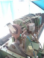
in the pic there is how the coil should be (not too extended) (upper sensor)
in the other pic the L shape metal have to be in that position , when the cut order is on that metal rotates and when it reaches that green sensor it should break and due to the inertia it moves little farther but it returns almost to the same place ,by rotating the cut is made ,i did have a problem which was that the green sensor did not detect the metal then i assumed that it was due the high rotation speed so i set filter to 0.1 and enable the option enable pulse catch then it works fine
what you think about the user program(code) ,tomorrow i will put it in the machine an d hope for the best

cutter.jpg dsdsdsd.png
 
What is the function of I1.5 (Upper sensor)?
What is I0.4 (Cutter in position), is that a sensor and how is activated?

https://www.youtube.com/shorts/mlalA3q3Gz0
https://www.youtube.com/shorts/PNvd7a8_L8E
if i use the CTU instruction or HSC i always get more 2 teeth ,when tell it to stop after 25 it stops at 27 ,i tried the same code in another mechanism with 18 teeth and it works great after 18 teeth it stops what i noticed is that the second mechanism is a bit slower just a bit
also in 25 teeth pinion when i rotate it by hand it disactivate the Q0.0 exactly when it reaches the 25 teeth (returned to the same start place)
so does the rotation speed cause me this problem,
also what i did is that substract 2 from 25 to get 23 ,so after 23 teeth +2teeth offset it will return to the same place but that does not happen
if the inertia was my problem it should return to the start place but it didn't
 
Can you take a video and/or pictures that actually show how the machine work.


Does every teeth equate to one slot movement of that plate?
When it goes over by two teeth, what is the counter value?


Are you saying there are two sensors, one to count and the other to stop? In the video you showed there's a sensor positioned to count teeth and in the picture you showed a sensor that is activated by a rotating plate.


This is what I understand:

Start command starts the motor, the gear turns and rising edge of teeth increment the counter. When the count is reached the motor is stopped but the counter will not reset until falling edge of that Prox that is activated by that rotating plate. So if the machine coasts the counter will register additional counts and if it continues to coast past that plate then the counter will reset.


If that is the case then remove all that code and put code similar to Network 1 and use the counter to stop the machine when count value is reached, just that one sensor. This will help you determine if the machine coasts or not.


I hope "ES" does not mean Emergency-STOP and I hope it is not wired in a similar way to how it is used in code. There are serious design and safety consideration for any safety device and an emergency stop could mean life or death.


You are troubleshooting too many things and making too many changes at the same time, some of it is helpful but it is always better to work on isolating problem areas.


I would start with cleaning up your code:

  • Do not use M-Bits to avoid any possibility of memory overlap with other tags including clock bits.
  • If you want global then just put them in a global DB and while you're at it give your existing DB a name that reflects its purpose; "." (dot) is not a name.
  • Do not use space in your names.
  • Give all your variables names that reflect their purpose so people reading your code do not have to keep going back and forth trying to figure out what "Tag_32" is supposed to do.
  • Work with one issue at a time. Small bits of code that can be tested and then add to it incrementally and test every segment you add.
Does every teeth equate to one slot movement of that plate: do you mean the L shape plate
the rol of the L-shape plate is when a given number of teeth's is reached the pinion stops then the cut motor engaged with that (brake/engage)mechanism
and when it does the mechanism AXE will rotate with the motor shaft by the same speed.(like the piston and crankshaft) rotary movement give you linear movement which will do the cat, so when L-shape metal rotate and reaches that green sensor a break order is made .
--When it goes over by 2 teeth the count value is 2 Both in CTU or HSC
I already tried a simple code when you reach a given teeth number stops immediately no counter reset just stop ,but always get 1-2 extra teeth
what about input filter time ,i tried many values but no great result
I also changed the mechanism with that one which worked fine with the 18 teeth pinion ,also no result
I will remove all the M bits and replace them with DB bits especially for edge detection instructions
also i think of going with (Enable rising edge detection) in the inputs which will activate a HW interrupt and in this HW interrupt the accumulation of the value will be made (am not so optimistic about this approach but am runout of options)
About ES it is emergency stop is there another safer way to programe it
 
Can you take a video and/or pictures that actually show how the machine work.


Does every teeth equate to one slot movement of that plate?
When it goes over by two teeth, what is the counter value?


Are you saying there are two sensors, one to count and the other to stop? In the video you showed there's a sensor positioned to count teeth and in the picture you showed a sensor that is activated by a rotating plate.


This is what I understand:

Start command starts the motor, the gear turns and rising edge of teeth increment the counter. When the count is reached the motor is stopped but the counter will not reset until falling edge of that Prox that is activated by that rotating plate. So if the machine coasts the counter will register additional counts and if it continues to coast past that plate then the counter will reset.


If that is the case then remove all that code and put code similar to Network 1 and use the counter to stop the machine when count value is reached, just that one sensor. This will help you determine if the machine coasts or not.


I hope "ES" does not mean Emergency-STOP and I hope it is not wired in a similar way to how it is used in code. There are serious design and safety consideration for any safety device and an emergency stop could mean life or death.


You are troubleshooting too many things and making too many changes at the same time, some of it is helpful but it is always better to work on isolating problem areas.


I would start with cleaning up your code:

  • Do not use M-Bits to avoid any possibility of memory overlap with other tags including clock bits.
  • If you want global then just put them in a global DB and while you're at it give your existing DB a name that reflects its purpose; "." (dot) is not a name.
  • Do not use space in your names.
  • Give all your variables names that reflect their purpose so people reading your code do not have to keep going back and forth trying to figure out what "Tag_32" is supposed to do.
  • Work with one issue at a time. Small bits of code that can be tested and then add to it incrementally and test every segment you add.

also to mention if i ask for a stop after 25 teeth and rotate that pinion by hand it did stops after 25 teeth and back to it's start point
 
M100.2 is set when counter preset value is reached. It resets Q0.0, the dragging motor and it sets Q0.2 that does the cutting. And what I understand from your reply is that the cutting is done by rotating something which the plate is attached to, and when it reaches the product and cuts, that plate activates I0.4 which reset Q0.2 to stop the cutting and resets the counter and the M100.2.

That brake/engage mechanism has to do with the cutting process, right? It is not a brake that stops the dragging, or is it? A brake means to stop something usually with friction of some sort, like a car brake.


And when I asked about teeth and slots, I meant the slots in the plate/product you are cutting. Does every tooth of that gear equal one slot movement of that product that you are cutting. What I am trying to determine is how much do those extra counts amount to.

And again, we do not know how fast the machine is running. If the machine is coasting after stop command then you have mechanical problem that has to be fixed mechanically but If the machine/sprocket is turning faster than the PLC cycle time then that can be fixed with code.

When an E-Stop is engaged (open circuit) nothing ever can move the machine, not in code and specially not know in real life/hardware/motors/current. This is not a safety PLC so the E-Stop input allows you to update the code accordingly and to indicate current conditions and reset tags and values. But the actual machine safety must be implemented outside and my final note on that is that I am not an expert and safety matters do need experts, so take this as an advice to seek expert advice.
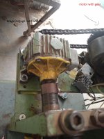
in the pic there is the break/engage mechanism for the 25 teeth pinion rotation ,the same mechanism is applied to the cutting motor
every teeth in the pinion equal one slot in the product
i think my problem is with the time cycle
what you think about using(Enable rising edge detection with its HW interrupt)in the digital input configuration

drag.jpg
 
At a scan cycle of 10ms that means your product is moving faster than 1meter/second and your sprocket is trurning faster than 4 revolutions per second (240RPM).
If that is the case you would not want to generate that many hardware interrupts and would be better off with HSC.
Do focused testing to determine speed and whether the product is coasting. For speed just configure the prox input as HSC input for single phase and set up the HSC for frequency and that should tell you how fast your sprocket is training.
 
On second thought, go ahead and hardware interrupt for the input at least for testing in minimal program and see what happens.
 
On second thought, go ahead and hardware interrupt for the input at least for testing in minimal program and see what happens.
https://www.youtube.com/shorts/xmG_CZ3pPHI

https://www.youtube.com/shorts/lsuGlxhQ6gk

https://www.youtube.com/watch?v=8vXzVvbYPX8

as you told me about measuring the frequency with HSC single phase the results are in the video which does not make sense ,so i measured the time for 1REV=25 teeth with phone and i got 0.97 to 1.3 s
so far we have tried many options with no good results

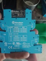
currently am using a slim relay to control that break/engage mechanism (pic) those kind of relays have delay on switching and the bouncing phenomena because it's a mechanical contact ,so what you think about using a solid state relay SSR

Slim Relay.jpg
 
Not that I think it will tell us anything we don't already suspect, but try adding a separate counter that counts teeth pulses, but only after the existing counter of pulses of teeth has reached 25, which is also after the PLC issues its stop output. I.e. The feed rung to this new post-stop counter includes a normally open contact of the stop condition (or a normally closed contact of the run condition).

It should count to at least 2, and most likely to 3, each time the main counter reaches 25.

If that is the case, then this problem is roughly analogous to spill in a filling application.
 
To read HSC frequency you have to read its memory not just look at the counts.


The machine stops with a snap, are you sure there is no brake on the motor?

In any case it doesn't look like it is coasting and with product dragged it is likely to stop even faster.


Here are two archived projects, V3 uses rising edge triggers and you should start with this one. It is very basic just is intended to test positioning; whether the sprocket stops on count. V4 uses HSC and does pretty much the same thing but I would suggest you start with V3 and make sure it works because I don't' have hardware and testing HSC without hardware is tricky at best.


You are working with live equipment so take all precautions as none of this has been tested.
 
Here is a link to a .gif of how to use the program.
Download the program as is to your controller, I set the hardware for S7-1215 DC/DC/DC V4.3. If you have later version you can still download this without any changes.

  • Download the hardware configuration.
  • Open DB_ControlTags and change the tag "Start" to True.
  • The motor should start turning and the input should start counting up to 25 at which point it will stop for 10 seconds then the motor will start again; on an on until you change Start to False or hit the E_Stop.
  • Note that changing Start to False will prevent the motor from restarting after it reaches 25 but if it is already running it will continue to run until the count is reached.
  • To stop the motor at any time the E_Stop has to be deactivated (circuit open)
Get this done first and then look at the rest of the process, cutting and whatever else.
 

Similar Topics

What would happen if you ran a 60Hz Single Phase Motor on 50Hz supply?
Replies
6
Views
533
Hi all, I am having a problem with a powerflex 753 we have on site and keep getting input phase loss. The drive has been running for a long...
Replies
7
Views
1,358
We have an existing VSD where a three phase circuit breaker feeds the drive, and two phases also tee off to a contactor, which is energised to...
Replies
12
Views
1,486
Hello all... I'm looking for a 480v 3ø 25+ amp Solid State Relay to replace a mechanical one beating itself to death keeping temp in a heating...
Replies
15
Views
1,964
Hello. We have a Powerflex 700s phase II firmware 4.002, but the encoder card is burned. We want to disable it to use the Drive without motion...
Replies
0
Views
454
Back
Top Bottom