PID - MicroLogix Temperature Control

... so you don't like the RG bit? ...

Greetings Peter and all,

I’m still trying to get in enough time to work on this thread ... one thing that I would like to add:

Peter said:
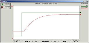
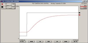
The RG bit is flawed!!!!!! Compare this trend with the RG bit set and the trend without the RG bit set in the first post. You can see the trend WITHOUG the RG bit set looks much better except for the coarse control.

I still haven’t had time to go over all of this in detail so maybe I’m missing something here ... but ...

I don’t think that the RG bit is flawed, Peter ... at least not on the SLC ... again, I don’t have a MicroLogix 1500 handy to experiment with ... but I just tried this experiment on an SLC-5/04 to confirm my thoughts ...

in a completely new program (without your simulator, etc.) set up two identical PIDs ... of course you’ll need two separate control blocks ... use a separate CV for each PID ... but use the !SAME! PV ... enter the !SAME! SP value for each PID ... in fact, go ahead and include a rung which will constantly MOV the !SAME! Setpoint into each PID ... what we’re obviously trying to do here is have two identical PIDs ... both looking at the same PV and trying to maintain the same setpoint ...

but for one PID, leave the RG bit OFF ... the Kc and the Ti entries will each have only !ONE! decimal point ... enter 2.0 for the Kc and 2.0 for the Ti ...

note: the RG bit doesn’t affect the Td (derivative) operation in any way ... ... (at least according to the book ... and I really think that it’s correct on this issue) ... specifically, the Td setting ALWAYS has two decimal places regardless of the RG bit setting ... let’s just leave Td set at 0.00 for now ...

for the other PID, turn the RG bit ON ... the Kc and the Ti entries will now each have !TWO! decimal points ... enter 2.00 for the Kc and 2.00 for the Ti ...

so even with the extra decimal point of resolution, we still should have the exact same tuning for each of the PIDs ...

now manually force the PV to equal the setpoint ... and set up a trend to simultaneously graph the response of !BOTH! of the PIDs ... and finally put the thing in the Run mode ... let the graph run for a minute or so to get a base line ... next change the setpoint of the two PIDs ... if you’ve set up the MOV rung that I mentioned earlier, then both of the PIDs should change at exactly the same time ...

and I believe that you’ll find that both PIDs will give EXACTLY the same response ... REGARDLESS of whether the RG bit is turned OFF or turned ON ... specifically, since both PIDs are looking at the exact same PV (input) and giving the exact same CVs (outputs), then we could surmise that the RG bit is NOT adversely affecting the response of either PID ... the CVs should be perfectly superimposed regardless of what you do to the PVs and the SPs ...

so what good is the RG bit anyway? ... it just allows us a little more resolution when we get ready to enter our Kc (Proportional) and Ti (Integral) settings ... and more resolution is always a good thing ...

I know it will be awhile before you get to work on this again ... but if you do get to run this little experiment on the MicroLogix 1500 and obtain any different results, please let me know ... but based on what I’ve seen on the SLC platform, I’d say that there is no flaw in the RG bit ... MAYBE there is on the MicroLogix 1500 ... but are you sure that everything else was set up the same when you made your observations? ... specifically, are you sure that you altered the original Kc and Ti entries to compensate for the extra decimal point? ... the entries will NOT automatically alter themselves when you turn the RG bit on or off ...
 
I stand by my charts posted above.

Ron, your test is not a valid test. Your test only checks for static situations. I think the problem or difference in response is due to how the differentiator filtering takes place. This requires a dynamic situation. See the plots above. They are using the same gains and responding to the same step jump from 100 to 350 degrees using the same model. You can see control signal from the charts are much different. I have a lot more faith in my model reproducing the identical responses than any manual method I can do. I expect the response to be like the chart with the RG bit off. When the RG bit is set you can see the output dips down too far and then back to steady state. WHY? ( I don't expect you to have an answer ).

I just re-verified my results. The plots above are representative of the difference between the RG bit being off and being on. Having the RG bit on still works, it just doesn't work as predicted. Most people would never know the difference. Using slow response like PhilipW one would certainly never know the difference. The next problem I have found is that I can increase the differentiator gain in an effort to keep the output from making the big undershoot, but it does no good. You can see I can calculate what gains are required to make a critically damped response for about any system or time to set point. (No ZN **** for me.) I can even calculate the time it takes to get within 1% of the SP or calculate would the gains should be to get with 1% in a certain time. If you remember, last year you bought a document on lambda tuning for $30. I call lambda tuning pole placement. I can calculate the gains that put the poles just about anywhere I want to get the response I want using pole placement or lambda tuning. I don't need to guess or use trial and error. I test my own PIDs with the same scrutiny.

When I come back I can redo my program on a SLC.

Now back to scaling. Obviously I have a method that works. You can see by the charts. I expect the SP and PV to be in degrees times 10. It is important that the SP and PV have identical units. I calculate a Kc in terms of %output/(degreex10) and multiplying by 16384 Dac counts/100%. Basically I calculate the gain in %/error unit and multiply by 163.84. This works well for my examples.

I hope that a few have run these programs by the time I get back on Friday.
 
SMC

Peter,

I have run the SMC and I like it. Nice and simple with no overshoot like the PID.
I have ran the following test:
N7:0 3500 to 4000 TC = 15 and this took about 4 min.
N7:0 4000 to 3500 TC = 30 and this took about 2 min.
N7:0 3500 to 4000 TC =30 and this took about 7 min.
Something I noticed is the ramp-up time versus the ramp-down times are different with the same TC and same step change. I need to look at the math and I am sure this will all make sense.

Thanks,
Bob O.
 
RG ... the bit that would not die ...

Greetings Peter,

concerning the RG bit ... I’ll admit that when I ran the same tests that you did (using your simulated Hotrod) I got the same results ...

specifically ...

test 1 was done with the RG bit turned OFF using these settings:
Kc=41.0 Ti=2.7 Td=0.63

test 2 was done with the RG bit turned ON using these settings:
Kc=41.00 Ti=2.70 Td=0.63

in each test the SP was step-changed from 100 to 350 degrees ...

the response of test 1 was exactly like the figure in your post #1
the response of test 2 was exactly like the figure in your post #9

and so I’m forced to agree that it certainly !LOOKS! like turning the RG bit ON does make a difference in the PID’s response ...

but ...

I just so happens that I wrote my own personal Hotrod simulator several years ago ... I’m not sure that I ever mentioned this on the forum ... and when I run the same “RG bit” tests on my simulator, then both CVs track each other precisely ... and also the PVs from both tests are identical with each other ... yes, this is significantly different than the results that you and I both obtained using your simulator ... I’m not exactly what to make of THAT point just yet ... but incidentally, my simulator is much more elaborate than yours ... it includes the real-world Hotrod’s deadtime (yes, I know that you don’t like that terminology) and it also allows for load changes to the system by simulating more or less air flow over the heater ... but yes, there is a LOT more math in my simulator than in yours ...

so my present position is that turning the RG bit ON does NOT alter the operation of the PID ... all it does is allow us one more decimal point of resolution when we enter the Kc and Ti settings ... and so (even in SPITE of the evidence offered above) I still maintain that:

Kc=41.00 Ti=2.70 Td=0.63 with the RG bit turned ON ...

will give exactly the same results as:

Kc=41.0 Ti=2.7 Td=0.63 with the RG bit turned OFF ...

so as soon as I have time (hopefully tonight) I’ll fire up the real-world Hotrod and try this set of experiments again ... this time on something other than our simulators ... I’ll let you know what I come up with ...

in the meantime ... I suggest that you and I simply “agree-to-disagree” on this particular point and move on to other things ...
 
comparing Peter's simulator to the Hotrod ... part 1

Greetings Peter and all,

background:

several months ago Peter started another very interesting thread ... I posted a few graphs from the actual real-world Hotrod (specifically, NOT from a software simulator) ... here is one of those graphs for easy reference ...

this is from the real-world Hotrod device ...

[attachment]

this is a common test that is often performed as part of a loop-tuning procedure in order to gain some insight into a particular system’s characteristics ... most people call this an “open-loop” test because it is performed with the controller in the manual mode ... in other words, the control loop is NOT in full operation at the time this test is run ...

the X-axis of the graph above is 22 minutes long ... the air flow (system load) was kept at a constant 20% of full flow throughout the test ...

to begin the test, the Hotrod’s heater was manually set for 10% drive ... the Hotrod’s temperature eventually settled out at a constant (steady state) 115 degrees ...

next the Hotrod’s heater was manually increased to 80% drive ... responding to this sudden change in drive, the Hotrod’s temperature increased and eventually settled out at a constant (steady state) 375 degrees ...

the curve that the temperature followed is VERY similar to a standard “capacitor charging” curve that all electronics students study ...

there ARE, however, some significant differences between this “heat response” curve and a standard “capacitor charging” curve ... anyone who is sufficiently interested in this particular subject is invited to post specific questions ...

on to the next post ...

heat_ron_a.jpg
 
comparing Peter's simulator to the Hotrod ... part 2

using the same type of “open loop” test as in the previous post, let’s take a look at Peter’s simulated Hotrod ...

this is from Peter’s simulated Hotrod program ...

[attachment]

as before, to begin the test, the Hotrod’s heater was manually set for 10% drive ... the Hotrod’s temperature eventually settled out at a constant (steady state) 107 degrees ...

next the Hotrod’s heater was manually increased to 80% drive ... responding to this sudden change in drive, the Hotrod’s temperature increased and eventually settled out at a constant (steady state) 366 degrees ...

the curve that the temperature followed by Peter’s simulated Hotrod is VERY similar to the curve of the real-world Hotrod ...

but ...

one highly significant difference that concerns me, however, is the lack of “deadtime” in Peter’s model ... this deadtime is the length of time AFTER the heater drive was increased BEFORE the temperature began to change at all ... on the real-world Hotrod, this “lag” is due to the physical length of the “rod” itself ... specifically, the “rod” is a steel screw approximately one inch long that replaces the original tip on the Hotrod’s “soldering iron” heater ... so even though the heater might be instantly increased from 10% to 80% of full drive, the thermocouple at the end of the rod can NOT possibly sense any increase in temperature until enough time has elapsed for the heat to travel the full length of the screw and start affecting the thermocouple sensor ...

but everything considered, the “open loop” test shows that the characteristics of Peter’s simulator are VERY CLOSE to the characteristics of the real-world Hotrod ...

on to the next post ...

peteropen.jpg
 
comparing Peter's simulator to the Hotrod ... part 3

this shows another type of common test that is often performed as part of a loop-tuning procedure in order to gain some insight into a particular system’s characteristics ... most people call this a “closed-loop” test because it is performed with the controller in the full automatic mode ... in other words, the control loop is actually sampling an input from the process and controlling an output at the time this test is run ...

this is from the real-world Hotrod device ...

[attachment]

the X-axis of the graph above is 22 minutes long ... the air flow (system load) was kept at a constant 20% of full flow throughout the test ...

to begin the test, the Hotrod’s PID was given a setpoint (target) of 200 degrees ... the PID was tuned for an abnormally high Proportional Gain of “327.67” (the MAXIMUM value available) for Kc ...

NOTE: this extremely high setting for proportional gain is NOT usually recommended practice in the field ... certain machines can literally tear themselves to pieces if treated this way ...

continuing on ... the Integral action was turned off by entering a setting of “0.00” for Ti ... the Derivative action was also turned off by entering a setting of “0.00” for Td ...

these extreme settings cause the PID’s output to cycle from full off to full on ... in simple terms, we’ve forced the PID controller to act as a common ON/OFF controller ...

under these conditions, we see that rather than settling out, the real-world Hotrod’s temperature continuously oscillated above and below the setpoint ...

once again, the purpose of this particular test is simply to gain some insight into the operating characteristics of the system ... the length of time (the period) between successive oscillations is a VERY important characteristic to consider when preparing to tune a control loop ...

incidentally, the period of oscillation obtained from the test above was 3.54 minutes per cycle ...

on to the next post ...

heat_ron_c.jpg
 
comparing Peter's simulator to the Hotrod ... conclusion

this shows the same “closed-loop” test as in the last post ... but ...

this is from Peter’s simulated Hotrod program ...

[attachment]

the X-axis of the graph above is 22 minutes long ...

to begin the test, the Hotrod’s PID was given a setpoint (target) of 200 degrees ... the PID was tuned for an abnormally high Proportional Gain of “327.67” (the MAXIMUM value available) for Kc ... as before, the Integral action was turned off by entering a setting of “0.00” for Ti ... the Derivative action was also turned off by entering a setting of “0.00” for Td ...

under these conditions, we see that rather than continuously oscillating, Peter’s simulator eventually settled out at the PID’s setpoint ...

this is not good ... the real-world Hotrod would have kept right on oscillating ... the fact that the oscillations of Peter’s simulator eventually died out indicates that the simulator might not be a valid model of most real-world temperature processes ...

based on this, Peter, I’d say that there is some fundamental flaw in your simulator ...

DISCLAIMER! ... I don’t have a MicroLogix 1500 available right now to just “plug-and-play” your simulator program ... so I’ve adapted your original code to run on an SLC-5/04 ... I !THINK! that I’ve made an accurate “one-to-one” transcription ... but !MAYBE! I dropped a stitch somewhere along the line ... if so, I sincerely apologize ...

once again, I don’t think that your simulator (at its current level of development) is acting enough like a real-world process to serve as a valid test for the PID function ... look at it this way ... let’s assume that I’ve made an accurate transcription of your MicroLogix program over to the SLC-5/04 platform then ...

suppose that “Doofus Dave” was assigned to tune your simulator ... all he’d have to do to get “close enough” to satisfy the requirements of many industrial heat applications would be to turn off the Integral and Derivative actions and then crank up the Proportional gain to WIDE OPEN ... and the darn thing would track the setpoint close enough to make most bosses happy ...

back in post #10 PhilipW said:
I must have used 100's of PID loops in SLC, Micro and CLX. Overall I find them simple, stable and dead easy to use as long as I ensure the loop update times are correctly handled.

I can’t say that I’ve personally used 100’s of them, but I know for a fact that the darn things DO work ... in post #6 you said that you were interested in my comments ... I sincerely appreciate your confidence ... right now I’m forced to humbly submit that I think that your simulator needs a little bit more work ... the “open loop” test looks good ... but I’m concerned about the total lack of deadtime ... the “closed loop” test doesn’t look so hot ... at least it’s not close enough to the real-world Hotrod’s characteristics to serve as a realistic simulator ... my gut instinct is that if you’ll take care of the deadtime issue, then the oscillations will fall into place ...

finally ... maybe I’m wrong about all of this ... and that wouldn’t bother me a bit ... but so far, I can’t see where any of my logic is flawed ... but I’m always ready to learn something new ... thanks for taking on this tricky PID subject ... we ALL appreciate your efforts ...

peterclosed.jpg
 
Re: SMC, GOOD SHOW.

Bob O said:
Peter,

I have run the SMC and I like it. Nice and simple with no overshoot like the PID.
I have ran the following test:
N7:0 3500 to 4000 TC = 15 and this took about 4 min.
N7:0 4000 to 3500 TC = 30 and this took about 2 min.
N7:0 3500 to 4000 TC =30 and this took about 7 min.
Something I noticed is the ramp-up time versus the ramp-down times are different with the same TC and same step change. I need to look at the math and I am sure this will all make sense.

Thanks,
Bob O.

Bob O. First share your success. Where is the trend chart?

There is nothing wrong with the math. If you notice the heat up and cool down time will vary depending on the temperature range. Think about this:

1. In my example I am working with temperature in the range of about 70 to 440 degrees. The cool down rate will be MUCH faster when starting at 440 than when starting at 100 because the difference in temperature between 400 degrees and ambient is very large which will cause heat to be lost faster that if the difference in temperature was small.

2. When heating up it will the temperature will increase MUCH faster when starting at 100 degrees and very slowly when starting at 400 degrees.

In short the rate of increase or decrease in the temperature will change depending on the current temperature while the heater is constantly on or constantly off. The SMC only controls the rate when close to the set point. At this point the the SMC controller trying to keep the switching variable s close to 0 and is in the sliding mode. When the heater is constantly on or off the SMC is in the 'reaching' mode. In any case the system can't cool down any faster than when the heater is constantly off and it can't heat up any faster that when the heater in constantly on. SMC ramps as fast as the system allows when in the reaching phase.

Bob O. Don't you think Rockwell should have a SMC block?
 
So why are the two trend charts different?

Ron, since I am away I can't check against my ML1500, I can recheck my numbers. A digital simulator is never perfect because is samples at discrete time but in this case the 1 second update rate is MUCH faster than the shortest time constant which was your sensor time constant of 1 minute, what I called tau0.

I can use the values to calculate the response in the time domain and compare that with the iterative results. Until I get back this will have to wait. However, I have a lot of confidence in the simulation.

If you have your program working on a SLC, have you tried ramping from 100 to 350 degrees using the same values I did as documented in my word document? This would verify you modified the program correctly.

Got to go excercise and set up the training room.
 
Ron, we have a problem.

My results with Kc set to 327.67 match yours. However, I did a simple stabilty check by looking at where the poles are. If the poles are in the left hand plane in the s domain then the system is stable even if Kc is set to 327.67. Yes, it oscillates but eventually settles on the set point.

BTW, when Kc = 327.68 this equates to a gain of 20 %ouput/degree

Code:
327.68 DAC counts     10 AtoD count    100% output         20%output
----------------- x --------------- x --------------    =  -------
1 AtoD counts         degree           16384 Dac COunts    degree


My conclusions. The gain and time constants of the model I am using are NOT those from your 'Hot Rod' system. The values I am using are:

Gain=3.69 degress/% ouput
Tau0=1 minute
Tau1=3.41 minutes

I do think my implementation of the model using the above values are accurate. If your 'hot rod' system truely oscillates then I think we need to recalculate G, tau0 and tau1. Note, not every system will oscillate without end.

Even so, no one has explained the differnce between the two trend graphs above, one with the RG bit set and another with the RG bit off. You should be able to verify the response is different yourself.
 
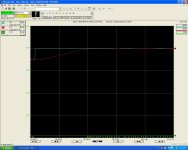
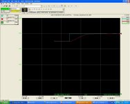
Figure 1 3500->4000 TC = 15
Sorry the pictures are so big. I tired the shrink them but then lost readability

[attachment]

3500 to 4000 tc 15.jpg
 

Similar Topics

Hi Everyone. I have been reading through the forums, and I have learned a lot! I do have a specific question that I couldn't find. I have a...
Replies
8
Views
5,115
HI - I have a tough process and have been struggling with controlling my PV using a Micrologix 1400. I uploaded the file, changed .rss to .txt...
Replies
9
Views
2,010
I have 2 no.s Micrologix PLCs used for PID control variable output to 7 no.s VFD drives.2 no.s are used as i have no spare analog cards for analog...
Replies
3
Views
1,536
I'm trying to get my PID function to go into manual mode and give the CV a value through a MOV instruction. I can set the Auto/Manual bit, and the...
Replies
3
Views
1,659
Hey guys, After spending most of a day Googling looking for the answer, I finally decided to make a thread and ask the experts. I'm trying to...
Replies
5
Views
3,575
Back
Top Bottom