GalacticPigeon
Member
Hi all,
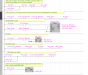
I'm having a bit of difficulty when it comes to the final question of my assignment, and wondered if anybody could shine some light on it for me. I've been trying and trying for hours but just cannot seem to get my head around it, to the point of I'm questioning everything I'm doing now.
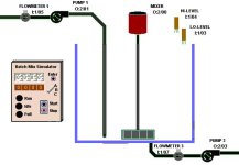
Any help in this would be MASSIVELY appreciated. (I have included the attachment of the image in reference to 'the application above illustrates...')
Below is the assignment question:
The application above illustrates a simple stirring application in a lemonade factory.
a)Use LOGO to design and build the above system, using function block or ladder logic, which will control the operation as follows:
When the Start ‘push to make’ (not toggle) switch (I1) is pressed/released, and gets latched on (B1: RS latch), the start ‘fill’ pump (Q1) will be energized and the tank will start to fill.
The pulses generated by flow meter 1 (B5: pulse generator) should be used to increment the counter (B6: Up/down). Tank level full is when the counter function on = 10 and tank low level is when counter off = 1. These values can be used as feedback to control the pumps (instead of the high/low level sensors shown above) and can be called the ‘tank high/low level count indicator’ (Q5 or use a flag M1)
When the full liquid level in the tank is sensed by the tank high/low level count indicator (Q5), the fill pump will be shut-off and the FULL light (Q2) on the control panel is to be energized.
When the tank is full, start the mixer (Q3) and run for 10 seconds (B8: off-delay timer).
When the 10 seconds has expired, stop the mixer (Q3) and start ‘empty’ pump P3 (Q4).
Pump 3 (Q4) will be required to run until the tank is empty.
The pulses generated by flow meter 3 (B15) should be used to decrement the counter (B6: Up/down). Tank empty can be detected by the high/low level count indicator (Q5 or use a flag M1) to switch off the pump
When the stop button (I2) is operated, the process must stop immediately (Q1, Q3, Q4).
b)Test your LOGO build and comment on your testing using LOGO simulation mode. This requires at least 3 print-screens of testing the system using the LOGO simulator below at the filling, mixing and emptying stages
Many thanks in advance!
Ross


