Transfer Pump PLC programming in Siemens Logo

jillgeorge18

Member
Join Date
Feb 2016
Location
Cochin
Posts
26
Hi there, I have three pumps, I have to start first pump for 8 minute and after that it should be turned off and other one start simultaneously and it should be run for 8 minute and same must be turned off after the time delay and the now 3rd one should start for 8 minute and should be turned off after the time delay and process would continue from beginning...Any help...Thanks in advance...All this based on float switch in tank
 
Last edited:
Sounds like homework to me...

What PLC platform?

If there are no other run conditions, then implement a 480 second timer that resets automatically when done.

When timer is done, increment an integer register by 1. When the register is greater than 3, move a value of 1 into the register.

This register is your pump number to run.

When register = 1, pump 1 called to start.
When register = 2, pump 2 called to start.
When register = 3, pump 3 called to start.

Check for register out of bounds, and move in a "safe" number, i.e. 1.

Good luck
 
Ah OK... float switch complicates things. Is it "start on high level", and then run for 8 minutes, or run for 8 minutes while the float is made?
 
Thank you for your response...How to timer resets automatically...Thanks in advance...
This is my simple program that I attached in the link below...
I have a float switch, tank is bigger one, so there are three pumps, that start and stop in a certain time delay...
for testing I put 5 seconds, but you have any idea about how to reset the retentive timer..
passionateelectricalengineer.blogspot.com
 
How to timer resets automatically...but you have any idea about how to reset the retentive timer..
passionateelectricalengineer.blogspot.com

  • To reset a timer, run a 1 to the R (Reset) input.
    • For example,
      • connect the Q of the retentive timer back to its R input.
      • When the timer expires,
        • Q becomes 1,
          • So the timer's R input becomes 1
            • which resets the timer.
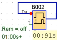
You could have a 1s repeating on-delay timer and count each time that timer expires; note the red dot that inverts the trigger input below, so

  • when Q=0, Trg is 1 (= NOT Q = NOT 1) and the timer runs, ...
  • ... until Q=1 because the timer expired,
    • at which point Trg becomes 0 (= NOT Q = NOT 1)
      • which resets the timer,
        • and the process starts over.
xxx.png
"It's just zeros and ones, it cannot be hard" - Jouni Ryno
 
Even simpler than a repeating 8min timer, program a 24min timer, and run pump 1 when the accumulated time is less than 480s (8m), run pump 3 when the accumulated time is greater than 959s (16m - 1s), run pump 2 when pump 1 and pump 2 are not running*.

You will also need the start/stop circuit pattern; see this link;

  • the High Level switch opening is the start element
  • the Low Level switch being closed is the stop element
    • So the Low Level switch being open is the [NOT stop] element
  • A stored boolean/bit is the Run and seal-in element, and will be ANDed with whatever circuit makes the timer run, and also with the pump run logic.
Update: it looks like logo has limited capability to do math and comparisons, so I suggest three counters counting seconds (Cnt inputs are fed by the Q of a 1s repeating timer).

  • The 1s repeating timer runs when the RUN bit is 1
  • Counter 1 counts to 480 (8min), using the repeating timer's Q bit
  • Counter 2 counts to 960 (16min), using the repeating timer's Q bit
  • Counter 3 counts to 1440 (24min), using the repeating timer's Q bit
  • All three counters are reset by the Q output of Counter 3
  • Pump 1 runs when
    • BOTH the Q output of Counter 1 is 0
    • AND the RUN bit is 1
  • Pump 3 runs when
    • BOTH the Q output of Counter 2 is 1
    • AND the RUN bit is 1
  • Pump 2 runs when
    • Pump 1 is 0
    • AND Pump 3 is 0
    • AND the RUN bit is 1
It could also probably be done with sequential start/stop circuits triggered (started) by the expiry of an 8min counter and the previous pump running, but that would always restart pump 1 first on a transition from 0 to 1 of the RUN bit.
 

Similar Topics

I'm trying to verify a project with a PLC. The Transfer Setup menu item is grayed out and every time I click Verify with PLC, I get an error...
Replies
1
Views
53
Hello, I need to create an automatic transfer panel that connects to the generator when the mains power is cut. I can draw up to 60kW and draw up...
Replies
0
Views
84
Does anyone know what the data transfer rate for this series of CompactLogix PLC's? 1769-L24ER-QB1B to be exact. Cheers.
Replies
1
Views
98
Hi all, Im having trouble transferring a program from one panelview 550 to an new one. I can insert a flash card into the old panelview and upload...
Replies
20
Views
351
Hi Everyone, I have a customer that needs a CQM1H (CPU51) replaced. They purchased the processor new-old-stock from a source they found online...
Replies
3
Views
351
Back
Top Bottom