PLC-programming problems

randylud:

Let's take this one step at a time. You have written code to make the linear unit move, but nothing more. Could you post that code so we can look it over?

If you check the FPWin Pro Programming manual (found on http://www.angelfire.com/falcon/soder/index.html) or check the pictures I attached - you can see something called a DUT. This has a variable called 'Control code' wich has a hexadecimal code for some instructions to the linear unit, or more precisly the servo motor.

What we found was that with the function F174_SP0H we could change this variable-code from 1200 to 1201 to make the motor go CW to CCW (clockwise/counter clockwise). Our idea was then to send a pulse to the motor to go CW e.g. Then we had a timer for 4 seconds, and then we changed the drive-direction to CCW. Just a simple program as it seems, but although we were able to send the unit to the left in one program and to the right in another - we were unable to create a program that went left-right-left-right and so on..
This shouldn't be to hard, but still - we're unable to do it.. :(


Would be glad if anyone could help us,

Thanks,

//Andreas
 
Laurent:

Are we talking here about one axis only ? Please confirm.

We are - while testing - only using one axis, but in the final application we're supposed to use 2 axis.


Did you download (and open) the manuals I suggested

And about this, check the message above - we were unable to get enough info from these sources to control our linear units the way we want.
And what do you mean with 'NAIS fan'?

I also have samples showing all the tricks you're asking for.

Do you?
In that case we'd be very glad if we could take a peek at them :)


As far as I remember your project also includes a vision system. What about this issue ?

You're absolutely right. But this is something we have more control and knowledge about.. The thing is that we're supposed to connect a camera to a linear unit, which itself is connected to another linear unit so that the 2 units represents an X- and a Y-axis. This makes it possible to have "vision" over a large area simply by steering these linear units.
In the "vision-chapter" we have been able to make a C++ program that finds an object (predefined) and sends the coordinates via serial communication to another computer. When we have more control over our linear units we will try to make this program send its coordinates to the plc wich should steer the camera to be on top of the object (Try to think of it as a camera following a moving object).


//Andreas
 
Last edited:
Hello Soder,

All depends on the movements you plan to implement. Send some additional information about your goal.

Generally speaking you might first try to use a versatile function called F171 and see all the related I/Os. As you can read several mode can be performed. Then program a test program by managing each segment of your motion path independently with this function including a home return at the end. I strongly suggest that you write some sequential program (SFC or ladder, but identified steps!) and perform a movement at each step of this cycle by F171. You write as many F171 as needed or... take advantage from the fact that only one F171 function can access as many data tables you want by using an index as address modifier (no DUT required, see below).

Assuming that your test only involves the output channel number 0, check what happens or can be done before/during/after the movements to/with these data : R903A, DT90044+DT90045 (double word), DT90046+DT90047, and DT90052 (check bits functions and bits combinations to be written in hexadecimal codes). All these bits and words can be located in the special relays and special registers tables.

As for F174 each F171 instruction reads a data table beginning by a control code. Keep in mind: this is an hexadecimal value. Basically this offers several choices for the internal counters management attached to these functions : incremental, decremental, absolute... and so on. Some of these modes also refer to the way some related I/Os are driven (CW-CCW or pulse-sign for instance). For the frequency ranges... I guess you found the answer by yourself. You calculate this code by addition of the required bits or digits in hexadecimal mode (each group of four bits is a digit and takes values from 0 to F).

Programming : if it does not seem to you to be the most flexible way to succeed, you don't absolutely need to pass your parameters by the mean of DUTs (therefore this object is commonly used in IEC61131-3 tools and allows you to deal with named collections or arrays instead of only absolute memory addresses). For your tests you better play with a table of words (DT or whatever is available) accessed and modified (online) before/during the motion. Write the values manually or by your program with... any function providing an output in double word/integer type. You also may write your sample codes in FP-Win GR mode despite the fact you work in FP-Win PRO. Use basic function blocks: easier at first steps to troubleshoot.

F172 could also be useful for manual tests, MINAS drive adjustments or self-teaching procedures in jog mode. Notice: with F172 the output frequency can be changed while running. Compare the F174 function to F175 and F176. These two might become you best choice when will come the time to implement your two-axis motion management. At this step ask for additional manuals providing math and basics in motion control (i.e: FP Sigma Circular Interpolation, ARCT1F365EN japan v1.1 FP Sigma positioning unit,...).

In the FP-Sigma manual carefully check from p107 to p142. Also see from p85 to 89 for general information.

NAIS Fan: start from here http://www.naisplc.com and choose Download. The link should be available. As previously suggested also seek the Aromat site at http://www.aromat.com/acsd/index.html or http://www.mew-europe.com/index.html or http://www.mew.co.jp/e-index.html ...

Take a chance to get in touch with representatives in your country (Tel: +46 8 594 766 80) and ask for a programming manual (paper or pdf format, including FP0 and FP-Sigma - plus other PLCs - in a single document).

I hope this helps

Laurent
 
Okej, thanks for all the effort - we're trying to work through it, but we have another simple (perhaps?) question.

If you look at page 108 in the FP Sigma User Manual you can see the pulses sent on Y0 and Y1, now when we're testing a program we're unable to make the motor stop send pulses, or e.g if we only want to send exactly one pulse. Can you or anybody else tell us how to do that?


Thanks for all the effort - really appriciated!


//Andreas
 
more help

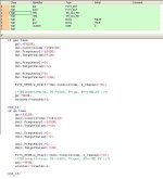
I'm attaching a small program which is supposed to go left then right then left then right... (the timers are commented out since we were trying to get it to work).
Anyway, the program doesn't work - the motor goes left about a microsecond, and then it goes right but never left again. The program doesn't either bother about the timer if we try to use one, does anyone know why? The timer works if we program in 'ladder diagram' or 'sequential function chat' but not in structured text!?

Please help us if you can, we're starting to get desperate :(


//Andreas

code.jpg
 
Hi Soder,

Sorry I just skimmed your program... but your timers can't run since they are not in the actual scan. Indeed as soon as you get "go" or "go2" you disable them and only launch the F174 function.

Regarding the motion and the way to stop the pulse generation... at least three methods are available (more upon special request) : DT90052 (most powerful), DT90044/DT90045 - elapsed value, DT90046/DT90047 - target value.

Each time you perform a movement the pulse generator doesn't stop until its elapsed value matches the target value (actually the target value is not totally fixed during the motion, but this is another story...). That's why you might use one or several or the three methods to stop the generator:
1) DT90044/DT90045 : write there a value very close to your target
2) DT90046/DT90047 : write there some value ... and check what happens (a little bit more subtle). If you succeed this allows you to stop with a deceleration.
3) Access to DT90052 by the mean of hexadecimal values... but first see your manual and the functions of each bit in this word!

Example : you write the value h0009 in DT90052 - the motor stops and the internal counter DT90044/45 is cleared. Immediatly after you write h0000 - you're ready for the next move. Try this with other values such as h0001, h0008, h0004 and so on. Check the bits 0 to 4 and all their combinations. Find by yourself the way to stop your motor without losing your actual position (necessary in absolute positionning).

Accuracy needed ? Write your stop code in an interrupt program. Want to stop immediatly when a position is reached? Try comparisons on your elapsed value, try time interrupt for improved accuracy, or try to perform home returns. Need for deceleration before you stop? Look for the built-in "near home" function.

Don't start to desperate! You have in hand an extremly interesting and challenging project!

And I'm back again with the same suggestion... play with F171 FIRST! You will easily get some good results by following your manual's examples. But you're the boss, aren't you...

I almost forgot... build an internal latch (Keep or SET/RST). Use R9013 and the R903A's falling edge in order to SET/RST the var. On each raising/falling edges of your var, perform a F171 in alternate directions (just change your control code or your target sign in absolute mode). That's it! You move from one side to the other one with a very short program.

Laurent
 
Hi.

Thanks for all the help. Now let's continue. ;)

First: we dont know what "type" we should use to write code in: ladder, instruction list, structured text, sequential function chart or function block diagram. Which is "the easiest" and which is "the best"? Or should we use different for different kinds of parts in the program?

Second: we aren't that god with interrupt programming. We have programmed interrupts with the PIC16F877 (in C code). Do you have any tip or small code examples we could use? Our "manual" isn't of much use for us. When I choose to create a new POU I choose "Program(PRG)" and then I have a lot of different Tasks to choose: No tasks, Programs, Interrupt 0, ... ,Interrupt 7, Timer Interrupt. Which should I pick? Is the different numbers only their priority, with the lowest number=highest priority?

should it be something like:
interrupt
....if timer1 is finished counting
........move unit
........start timer2
....end_if
....if timer2 is finished counting
........stop unit
........change direction
........move unit
........start timer3
....end_if
....if timer3 is finished counting
........stop unit
....end_if

main
....start timer1
....while 1
........(* do nothing: wont our program crasch here? *)
....end_while


Third: we have only managed to move the unit (and change direction and speed) by altering the Control Code and the frequency. We havent changed any registers (DTxxxx) or used R90xx. And we're having troubles doing so in every "type" except structured text (which we think looks like this:
DT90052 := 16#0009;
). I took a look at the DT9052 and I understod the "concept". Is this how I make the unit stop in my interrupts above?

ex
....if timer2 is finished counting
........DT9052 := 16#0008; (* stop unit *)
........change direction
........(* use F171 here? *)
........DT9052 := 16#xxxx; (* move unit *)
........start timer3
....end_if


Fourth: we havent figured the "home position" all out yet. On our units we have 3 sensors. One in each end and one at 1/4 of the length. Is that what means with "home"? And what is then "near home"? Or is this some "virtual value" that we write in our code (like a Target Value)? Is 0 = one end of our linear unit and e.g. 100000 = is the other end?


I appriciate all help. Thanks. =)

// Johan, Andreas' companion
 
Johan, Soder,

First: we dont know what "type" we should use to write code in: ladder, instruction list, structured text, sequential function chart or function block diagram. Which is "the easiest" and which is "the best"? Or should we use different for different kinds of parts in the program?

The way you build your analysis is fully yours. Obviously for sequences you might prefer SFC, but could write in FBD or even IL either. There is no choice definetly better than another one. If now you're talking about your drive management I would choose a mix between SFC (cycles and macro-analysis), ST (data management and calculation) and ladder (built-in function calls). At the end of the process despite the fact you used several editors your codes are translated in IL. You can check this in your navigator and figure out what is the ladder code equivalent to SFC or ST programs.

Second: we aren't that good with interrupt programming

Your program does not seem to be that difficult (based on Soder's explanations). I would be surprised that it requires an interrupt program. Also try to enlight this point: why do you want to control your motion by timers ? Basically you don't need timers. Only coordinates have to be defined.

In case you absolutely need to test your motor with a timer:
build a timer in any program editor, launch a F171, F174 or whatever you choose. At the end of the timer (pulse) you only write h9 in DT90052 than you write h0 in the scan. No interrupt required. Nothing more.

R0---(DIFU)---[F171 ....]
R903A------[TMX10 K50] <- timer 10, time base 0.1s, select value 50
R903A--T10--[F0 H9 DT90052]--[F0 H0 DT90052]

As soon as R0 is on the motor starts... and stops after 5 seconds.

But try like this (pretty accurate and much more simple):

R0---(DIFU)---[F171 ....]

That's it, assuming that your low/high freq are both 1khz and your preselection is 5000, 5000 pulses are generated in 5sec. My point is: now the final position is known and can be read. Use this method with different values of your low/high freq. Please... TRY IT right now!

I took a look at the DT90052 and I understod the "concept". Is this how I make the unit stop in my interrupts above?

Yes, it would be the best way for you to work. But also keep in mind that:
neither interrupts, nor timers, nor forced stop are required :cool: . In F171 mode your motion automatically stops when a target value is reached.

Keep it simple! Just play with the F171 and adjust: your control code, your frequencies, your target values. With a single set of data, you might achieve the whole job by only changing the target values in absolute mode: start from 0, go to 5000, go to 2000 (direction changes), go to 4500 (direction changes), home (see below). How to know that the motion is running: R903A is ON (channel 0). How to know that the target position is reached: falling edge of R903A plus current value of DT90044/45 matching your current target.

On our units we have 3 sensors. One in each end and one at 1/4 of the length. Is that what means with "home"? And what is then "near home"? Or is this some "virtual value" that we write in our code (like a Target Value)? Is 0 = one end of our linear unit and e.g. 100000 = is the other end?

Well, there is no rule... YOU actually do BUILD the rules. According to the mechanical "step" of your motion you might decide that one end of your unit is -3755 and the other one is +7269. It would be also nice that a sensor gives a mechanical zero in between. What happens when you plan to reach a position in an accurate manner? Let's say you're driving at 65mph, and suddenly brake when you're in front of an indicator. Your car wouldn't stop immediatly. You know that we all begin to brake far before the indicator, and this way can finally brake and stop. During the home return you want your motor to run as fast as possible. But you also may need to stop each time exactly at the same place. This is why a near home sensor is added. When this sensor is seen the motion slows down and finally reaches the home position at very low speed. No matter if you don't have any near home sensor. If you're looking for enhanced accuracy, this sensor can be simulated: during your home return, check your elapsed value. When the value is close enough to zero, then write a 1 in the bit 4 of DT90052 (DT90052 OR h10 --> DT90052).
Don't forget to erase the bit when the home return is achieved AND to use the differential counter clear output (wired to the servo-drive).

Johan, discuss with Soder. You should post here a schematic of your project (or one for each basic step).

Laurent
 
first working program

How to know that the motion is running: R903A is ON (channel 0). How to know that the target position is reached: falling edge of R903A plus current value of DT90044/45 matching your current target.

How can you tell what values are in DT9044/45? (we only have CT28 and not CT32 so we dont use DT90044... I think).

We have managed to make a program now that moves the linear unit for two seconds and then changes direction and increases the speed for another two seconds and then over and over again. When it has reached its max speed it decelerates instead. It stops after 20 loops.


(* Moves the linear unit two seconds in one direction *)
(* and then changes to the opposite direction for two *)
(* seconds and then changes back again. (The distance *)
(* travelled differs for each turn). Stops after 20 *)
(* loops. *)
(* JP & AS, 2004-05-13 *)

(* start *)
F171_SPDH(s_Start:=dut.ControlCode, n_Channel:=0);

(* falling edge *)
IF DFN(R903A) THEN
if count = 20 then
count := 0;
(* stop *)
word_to_sdt(In := 16#0009, Offset := 52);
end_if;

(* increase/decrease frequency *)
if count < 10 then
dut.Fmax := dut.Fmax + 5000;
else
dut.Fmax := dut.Fmax - 5000;
end_if;

(* change target (switch directions) *)
if count mod 2 = 0 then
dut.TargetValue := dut.Fmax;
else
dut.TargetValue := -dut.Fmax;
end_if;

(* go go go *)
F171_SPDH(s_Start:=dut.ControlCode, n_Channel:=0);

count := count + 1;

END_IF;


Here's another test program. It moves from side to side by accelerating/decelerating when it comes near the targets.


(* Acceleration/deceleration test. *)
(* JP & AS, 2004-05-13 *)

dut.TargetValue := 800000;

(* start *)
F171_SPDH(s_Start:=dut.ControlCode, n_Channel:=0);

(* falling edge *)
IF DFN(R903A) THEN

(* change direction *)
dut.TargetValue := 0;

(* go go go *)
F171_SPDH(s_Start:=dut.ControlCode, n_Channel:=0);
END_IF;


The DUT we have used for both this programs looks like the following:

(*FPWIN Pro:
VERSION:5.00.03*)
TYPE

F171_DUT:
STRUCT
ControlCode: DWORD:=16#1210;
Fmin: DINT:=1000;
Fmax: DINT:=1000;
AccelTime: DINT:=100;
TargetValue: DINT:=3000;
Termination: DINT:=0;
END_STRUCT;

END_TYPE

Values:

ControlCode := 16#1210,
Fmin := 1000,
Fmax := 100000,
AccelTime := 1000,
TargetValue := 10000000,
Termination := 0


Tomorrow we will test with two linear units at once.


One question: How do we do when we want to "change" target during a "run"? Or to test a change? Dont we need interrupts then? Like we run the above program and then X seconds in the program we want to change direction. Do you understand what I mean?

The point with our program is that it gets coordinats from the COM port all the time where to "object" is or has moved to. So we'll sometimes have to change target before we reached the previous target.


// Johan
 
You should post here a schematic of your project (or one for each basic step).

I dont know if this is what you mean - but I can post the document of the basic steps in how the final program is supposed to work - as we believe now anyway ;)


BASIC STEPS

Program with 2 linear units (2 axis system)

------------ Declaration


The end-position units should be declared as the ends.
connect sensors to X-output on plc.


------------ Calibration


The system should start at the top left corner, setting the top left pixel as coordinate 0,0
linear units travel as far up and left as they can until reaching end positions.


The system travels to bottom right corner, setting bottom right pixel to coordinate ?,?
(calculated based on the camera's coordinates.)

START (starting at top left position mentioned above)

get bottom left Y-coordinate from the camera image, travel down until that coordinate is set on cameras
0,0 coordinate.. repeat until "bottom limit sensor" is reached, set bottom coordinate from the camera to
the "total image Y-coordinate". (add camera coordinates to get "total image Y-coordinate").

get bottom right X-coordinate from camera image, travel right until that coordinate is set on cameras
"bottom,right-coordinate".. repeat until "right limit sensor" is reached, set right coordinate from the
camera to the "total image X-coordinate". (add camera coordinates to get "total image X-coordinate").


------------ Run-mode


Program gets "extraction point coordinates" from 'camera' (!!Camera coordinates!! e.g 121343 -> x=121, y=343)

By using a serial-communication-function, the coordinates to the "extraction point" is read by this program.


!!Interrupt!!
Everytime a new coordinate is recieved - the "extraction point" changes and the new
"input coordinate" becomes the "extraction point".


Travel to "input coordinate"
Check current coordinate, calculate where to go.
Current position is where the cameras center-coordinate is (e.g 320x240 in a 640x480 pixel image)
The extraction point is read by this program as a camera-coordinate (e.g max 640x480). This
coordinate is calculated and transformed into a coordinate in the "total image coordinate-system"


Destination in relation to current position:
"Far" negative position (left/up)
"Far" positive position (right/down)
"Near" negative position (left/up)
"Near" positive position (right/down)

Use an interpolation-function, travel the nearest way to position.
If "near" extraction point, decelerate for a smooth stop (near home?)
else
keep maximum velocity


------------


Thanks for all the help,


//Andreas
 
Hello Soder,

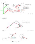
Find below a drawing in three parts.

The first drawing shows your motion as described in your last post. Each time you get a new set of coordinates (target) you plan to change your path. Attached to each target you may want to add a tolerable error range. Within this range a new target is not executed (V4 actually does not modify the move M3. M3 remains unchanged and becomes M4 only for the drawing). The vectors Vx are theoretical. The actual vectors are M1 to M6.

This can be achieved in several ways to be compared and tested. The resulting motions also depend on the refresh rate of your target coordinates. Your motion should be continuous as far as possible (neither unstable nor vibrating). Programming, timing and mechanical constraints may be considered.

Suggestion 1)
Independent axis both driven in F171 mode and basic maths. A constant composite speed is choosen. Acceleration time set at 30ms. Given an axis, low/high speeds always set at the same value. Absolute positionning. No interrupt required. Smooth motion due to an apparent linear interpolation.
  • * system is running (currently executing the vector Mn) R903A + R903B are ON
  • * new target received
  • * consider your target position Pn+1 (DDTx, DDTy)
  • * stop your two axis h8->DT90052, h2008->DT90052, h0->DT90052, h2000->DT90052. R903A + R903B are OFF
  • * consider the current position Pn (DDT90044, DDT90200),
  • * determine DeltaX and DeltaY and calculate the two relative speeds based on the constant composite speed
  • * restart channels 0 and 2 on F171 with new coordinates and speeds.
  • * new target locked
  • * loop while executing the vector Mn+1

Suggestion 2)
Same method with pre-determined speeds for both channels 0 and 2. Given an axis Low/high speeds are different. Accelerations set as required for smooth direction changes. Relative positionning. The absolute position is calculated. No interrupt. No interpolation. Paradoxically the motion may appear as being less jerky.
  • * system is running (currently executing the vector Mn) R903A + R903B are ON
  • * new target received
  • * consider your target absolute position Pn+1 (DDTx, DDTy)
  • * consider the current position Pn (DDT90044, DDT90200) and calculate the absolute position,
  • * determine DeltaX and DeltaY. Calculate the new relative displacements and directions (by signs).
  • * only stop an axis if its direction changes. Restart on F171 with the new relative target.
  • * direction is maintained: the new relative move is DeltaX or Y. Don't stop. Change on-the-fly your current position DDT90044 or DDT90200 by actual target(written in F171) - Delta. Automatically extends or reduces the range of your actual displacement.
  • * new absolute target calculated and locked
  • * loop while executing the vector Mn+1

Suggestion 3)
Use the built-in linear interpolation function F175. Stop and restart your two axis as soon as new targets are acquired. Composite speed automatically calculated. Absolute positionning. No interrupt.

Suggestion 4)
See the second drawing. Use the built-in circular interpolation function F176. Generates smooth moves. No stop. Absolute positionning. No interrupt. Each calculated linear vector is truncated in individual micro-vectors (Part "z"). The minimum length of these micro-vector is fixed. Linear sections: target+pass position method. Direction changes: center+radius+angle method. With F176 the target data can be overwritten after start-up. A new target acquisition will happen during a linear micro-vector execution. In case of direction change the end of the current "linear" vector will be the entry point of a circular path configured in "center+radius+angle" method. Center coordinates to be calculated.See the third drawing. Pass-point (continue) is set for all your intermediate targets, excluding the last move (stop) in case the motion stops.
  • * system is running (currently executing the vector Mn-Part"z") R903A + R903B are ON
  • * new target received
  • * consider your target absolute position Pn+1 (DDTx, DDTy)
  • * the current position Pn to be used is DDT90044, DDT90200 at the end of the current move. Actually this is the target of the current linear vector.
  • * Use a circle with fixed radius (third drawing). The target (output) linear vector is to be calculated. It begins at the center of the construction circle, ends at your target position.
  • * Determine Center coordinates, Radius and Angle of the intermediate circular path (math).
  • * Use R904E and R904F and change on-the-fly your target data blocks for the next circular move. Don't forget to set "Pass-point".
  • * At the end of your circular section, switch to target+pass position method and continue with the Mn+1-Part1 linear vector.
  • * new absolute target calculated and locked
  • * loop while executing the vectors Mn+1-Part"z"

Suggestion 5)
Improve the previous mode by mixing combining F175 and F176. Actually I can't confirm that this is feasible until you test and succeed in the fourth motion control mode.

Homing and safety issues:
Park your axis with F171. If you are looking for smooth approaches and accurate final stop combine both near home control and highly repetable sensors. Near home (meaning deceleration): see your manual for system registers, especially check DT90052. special bit should be set when the current absolute position becomes close to zero. Keep enough time for a whole deceleration completion. No matter if your axis don't home simultaneously (no interpolation required).

Safety: check if objects can be located on your path. Prefer hardwired safety chains and relay including your overtravel sensors (no PLC involved). Include special manual procedures for safety management and motion recovery if your safety relay happens to be reset by an overtravel sensor (i.e the direction should be forbidden until you reach the safe zone).

I thought that your last three posts deserved this detailed answer. The following step should be for you to post a running program including a realistic and functionnal two-axis management.

Good luck,

Laurent

motion.jpg
 
Laurent:

Thanks so much for the effort you're putting down to help us, I'm sure we will have great use for your tips =)

Although, we still have a few obstacles to get by before we're fully up and running.

First:
How can you tell what values are in DT9044/45? We havent figured this out jet..

Second:
We havent fully understod R903A and R903C.
Is it like this: R903A has a falling edge when the X-axis is in
position and the R903C has a falling edge when the Y-axis is in
position?

Third:
We tried making a program that should make the path look as a "square" if you follow.. That means that first the "Y-axis" moved down, then the "X" to the right, then "Y" up and last "X" left.. then the program should start over again.
We tried making this program using the interpolation-function F175, and for the correct moves we set the target value for the axis that shouldent move to the current value... this didnt work properly though, seems like R903A didn't get a falling edge!?

Fourth:
About these interrupts again..
When we're suppose to change the target valuesbefore they have been reached..
If we take an example:
unit is in point A
target is in point B
halfway to point B the target changes to point C
Now we dont want to go to point B anymore, we want to
change topoint C. But you say we dont need to do this by
interrupts? (The only time we're changing points is when we get data from the COM port. But aren't we supposed to check the COM port by
interrupts?)


Would be really glad if you could help us some more, seems like you understand our problems incredible well and we really appriciate everyrhing you've helped us with so far =)


//Andreas
 
How can you tell what values are in DT9044/45?
DT90044/DT90045 contain the elapsed value of the step counter linked to channel 0. This double word is addressed by DDT90045 in FPWinPro. Just read this value, load it in memory, or monitor it. Read/load: the method depends on your editor. Ladder: F1 (double word Move - see your manual). ST: variable assignment or more simple: declare EV_Channel0 as a double/integer/global var linked to DT90044/45. You read and write it wherever you want in the program. Generally speaking you just read the FP-Sigma manual and look for the function F1 in program samples.

R903A has a falling edge when the X-axis is in
position and the R903C has a falling edge when the Y-axis is in
position?
Actually yes! R903A goes ON as soon as a function related to the channel 0 (involving the positionning counter) is launched... and goes OFF at the end of the process.

We tried making a program that should make the path look as a "square"...
F175 may not be the most obvious way to achieve this... since there is no interpolation here! (Depends on the square's orientation in fact... why not re-try with a square and a 45deg angle?) What did you set up as a control code (absolute or relative pos.)? Keep in mind: if an axis does not start... it does not stop and the associated flag's state does not change! In such a case you better check a rising edge of [NOT(R903A) AND NOT(R903B)].

About these interrupts again..
You use interrupts when you deal with time-related issues and look for response times as short as possible. In such cases your progam can be "interrupted" by some external signal (meaning: sensor needed!) But first : what kind of external signal can you wire to an interrupt input? Also a PLC is not a computer. Your whole program + I/O management/refresh is fully executed at each scan. Guaranteed. If your FP scan is around 2ms (but less than 1ms is possible), it means that a coordinate change can be executed in less than 2ms when acquired. You seem to be confused between various possible meanings of the word "interrupt". Dig a little bit in the basics of PLCs. Several tons of posts around here will help you to envision this major issue.

Let's sum it up: I wrote that you don't need to program interrupts for several reasons.
a) there is no external signal to be used
b) what does it REALLY change whether your path change is executed within the current 2ms... or 1 or 2ms later?
c) the PLC scan is fast enough and guarantees short response times in this application for COM and data management as well.

My point is: you better look for a method allowing to change your coordinates on-the-fly WITHOUT STOPPING your axis. This will generate a very smooth motion and will avoid mechanical constraints or possible errors and step losses. Re-read my previous post and seriously try to test the Suggestion number 4 (or find an alternative solution).

Laurent
 
We've now managed to move the units in a octagon-shaped path. Here's the code:

----------------------------------------------
Main

DUT (PULSE LINEAR):
ControlCode := 16#1010,
InitialSpeed := 10,
MaximumSpeed := 100000,
AccelDecelTime := 300,
TargetValue_X := 0,
TargetValue_Y := 0

(* Moves the linear units in a octagonal shaped path. Dual action. *)
(* JP & AS, 2004-05-18 *)

(* falling edge at x- or y-axis, or first time *)
IF DFN(R903A) or DFN(R903C) or runonce THEN
runonce := FALSE;
(* change direction *)
ChangeTargetXY(DUT_In:=dut,DUT_Out=>dut);

(* go go go *)
F175_SPSH_LINEAR(n:=0, s:=dut);
END_IF;


----------------------------------------------
ChangeDirectionXY

DUT_In := PULSE LINEAR (input)
DUT_Out := PULSE LINEAR (output)
(the coordinates for a octagonal shape:)
pos := ARRAY [0..7, 0..1] OF DINT = [1,0,2,0,3,1,3,2(2),3,1,3,0,2,0,1]

(* move to the next node in the path *)
DUT_Out := DUT_In;
(* change target values *)
DUT_Out.TargetValue_X := pos[count,0]*30000;
DUT_Out.TargetValue_Y := pos[count,1]*30000;
(* increase counter *)
count := (count + 1) mod 8;


----------------------------------------------

Now we have a few questions:

*) Coordinates. How do we tell the system where the (0, 0)-point is? As it is now it seems to be moving from run to run. Is there a way to calibrate it? Perhaps use the Home-sensors?

*) Sensors. We also managed to connect the sensors (three from each linear unit) to the PLC. But we aren't sure to which "input signal" we should connect to. The manual say that X2 and X5 are for performing a hardware reset. But we found some strange text that says the opposite. So now we arent sure about it.

"A hardware reset disable is only effective when using the reset inputs (X2 and X5). In all other cases it is ignored."

If we disable the hardware reset (Do we have any use of it?) can we then use the X2 and X5 input as normal inputs? We also read that the X0-X7 has quicker response time so that noise and disturbances could appear as signals. should we change into XA-XC and XD-XF as input signals from the linear units?

Or should we connect both end-sensors on the x-axis to X2 and both end-sensors on the y-axis to X5 and then let them reset the counter by them selfs (And no "code" from our side)?

Now we have connected the input to X0 (home), X1(end), X2(other end) and X8, X9, XA. Does this matter in any other way then the name of the varible when we program?

We want to accomplish to "stop" the counter when a unit has reached an end. As it is now the PLC think that the unit has moved all the way when it hasn't. We plan on doing this by checking if a X-signal is high (or low) and then stopping the counter. Is there a better way?

*) I have also tried to determine and change the values of the DT90xxx registers with 50% success. This code below is my "debug/watch" code:


VAR_GLOBAL
EV_Channel0 AT %MD5.90044: DWORD:=0;
EV_Channel2 AT %MD5.90105: DWORD:=0;
TV_Channel0 AT %MD5.90046: DWORD:=0;
TV_Channel2 AT %MD5.90107: DWORD:=0;
HSC_ControlCode AT %MW5.90052: WORD:=0;
END_VAR

(* Move unit here *)

(* "output" for Ch0 *)
EV_Channel0 := EV_Channel0;
TV_Channel0 := TV_Channel0;

(* "output" for Ch2 *)
EV_Channel2 := EV_Channel2;
TV_Channel2 := TV_Channel2;


When I use a simple program to move both units from side to side then I get values in Ch0 but not in Ch2. I have changed from Ch2 to Ch1 and Ch3 but nothing. It only shows 0000 in both EV and TV while the first shows current pos and target pos. Any idea why?


Thanks again for the help. Our next step is to look deeper into circular interpolation and make it work. Though we dont know how to "simulate" the change of target whilst we move towards it. But we will sure come up with something. Or perhaps we'll make the COM communication work and use it to send new targets.


//Johan.
 

Similar Topics

I am currently editing a PLC program that was written by somebody else. Unfortunately I am no expert on PLCs, but can usually get by. The PLC...
Replies
5
Views
6,330
Hello colleagues, Some time ago I started my adventure with programming. With your help and the courses, things are starting to come together...
Replies
13
Views
691
Dear All, I need a sample PLC program to count the output pulse of a mass flow meter so that a specific amount of mass (for example 100gm)can be...
Replies
2
Views
158
Hi Please I have zeilo smart relay #SR2A201BD but I don't have it's programming cable. Can I use any general usb/rs232 converter? Or need...
Replies
3
Views
167
Hi, Does anyone have thoughts or know of, can point in the right direction any published materials with a plumbing centric point of you explaining...
Replies
1
Views
170
Back
Top Bottom