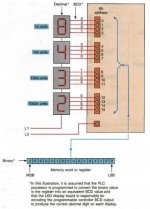
plc seven segment display project

Join Date
Jun 2011
Location
florida
Posts
53
Q I am brand new to plc's but I had a couple courses in college. Any help in detail would be much appreciated.

What I would like to do is make a 7 segment display and have my plc tell it what numbers to display based on a timer or count down. I've read that you can hook up each of the seven segments to their own output port on the plc. I understand how that can now make any number based on which outputs are energized. What I don't understand is how or what the best way to tell the plc is to turn on those outputs. I would like to be a ble to push one start button which would start an internal 30 second count timer and simultaneously have the outputs light up the numbers as it counts down (9, 8, 7, 6, etc.)

I hope some of what I explained makes since because I really would like to know how I can do this. I also hope that what I want do is as easy as I think it should be. Do you think it's doable?

Thanks David
 
What PLC are you using?

Make and Model, and what Programming Software you are using.

Have you picked out a 7 Segment Display yet?

If so, what Make and Model?

Depending on the Module, you will need a 5VDC or 24VDC Output Module, either Sourcing or Sinking.

Stu....
 
I'm just sort of getting back into plc's so I don't really have anything yet. I bought a micro logix 1000 plc trainer and I am using that to try out a lot of programming techniques. I plan on buying a bigger plc to do what I am talking about. It will probably be another Allen Bradley model. I am programing with rslogix micro light now because that is what my trainer came with. I will probably use rslogix 500 if I get another ab plc. I hate to sound like such a beginner but Im learning alot of this on my own as I go.

If I buy 7 segment displays, can the individual segments be wired separately into the different output ports of my plc. I ask because I have never worked with store bought displays. I was actually planning on , making my own make shift segment displays using some kind of lights that I position on a board to form a seven segment display.

That's what I had in mind anyway for two reasons, it sounds simple to me, and I need to make it fairly large and see-able in outdoor conditions.

I guess what I'm really looking for right now are ideas and suggestions
 
Last edited:
Yes, you could use 24VDC, or 120VAC Pilots to make up your 7 Segment Display. This depends on what kind of ML1000 you have. Then connect each one to an Output.

The AB PLCs do not have a direct 7 Segment type Instruction that I know of. The closest is the DCD Instruction, so you will have to build one. Do a Google Search for 7 Segment Display Truth Tables to see which Outputs you need to turn on for each Digit.

Stu....
 
Don't know if this is the esiest way but this is how i would do it.
First you need to map which segments ie. outputs are needed to produce the numbers you want.
After that you use memory blocks to activate the right number when you want.

I'm not familiary with logix programming but if it's like siemens the counter has a BCD-number output which you could compare to a fixed value and set the correct outputs.
 
Ive been trying to do some google searching on how to use the dcd instruction and where to build a truth table in the plc program but somehow I must not be looking in any of the right places. I will just have to wait for this weekend when I can dig up my old PLC text books from college. I remember going over some parts of that but its just not ringing a bell for me right now.
 
I think you should use brute force for practice.

Write the program from right to left ;)

Start with the outputs. 7 of them. Seven OTE instructions each on its own rung.

Next: think of each of the values you want to represent and start with zero. To make the number zero, which of these segments needs to turn on? Add instructions to all of those to allow the lights to light when the value is EQU to zero.

Next, add branches around those EQU instructions and place on the branches EQU instructions looking for "1" to each output rung for segments required to make a "1". There should be two of them. Then add more branches for each of the other numbers or symbols you want.

If you want to edit like a pro, add the first branch then put the cursor on the corner before the EQU and hit CTRL C, and then hit CTRL V as many times as you need branches for each segment. This will copy and paste branches each including the EQU instruction. Then go edit the compare values in the new EQU blocks, and delete the empty "shorted" branch. Working this way, you would write the code faster, and process each segment by asking your self "which numbers am I looking for to light this section?".

You can combine parallel branches into LIM blocks to shorten the code more.
 
Last edited:
I think you should use brute force for practice.

Write the program from right to left ;)

Start with the outputs. 7 of them. Seven OTE instructions each on its own rung.

Next: think of each of the values you want to represent and start with zero. To make the number zero, which of these segments needs to turn on? Add instructions to all of those to allow the lights to light when the value is EQU to zero.

Next, add branches around those EQU instructions and place on the branches EQU instructions looking for "1" to each output rung for segments required to make a "1". There should be two of them. Then add more branches for each of the other numbers or symbols you want.

If you want to edit like a pro, add the first branch then put the cursor on the corner before the EQU and hit CTRL C, and then hit CTRL V as many times as you need branches for each segment. This will copy and paste branches each including the EQU instruction. Then go edit the compare values in the new EQU blocks, and delete the empty "shorted" branch. Working this way, you would write the code faster, and process each segment by asking your self "which numbers am I looking for to light this section?".

You can combine parallel branches into LIM blocks to shorten the code more.

After playing around on my trainer some more, I was successful in testing your method. It's slowly starting to come back to me with more practice. I'm super happy that I'm finally able to get some life into this project. It's been something I have wanted to build for a while now. It's late now and I got to work in the morning but I will continue working on this tomorrow.

Thanks, David
 
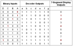
David, This picture (might be from your old PLC textbook) will help refresh your memory about how a 7-segment encoder has to work.

7-Segment LED- R1.JPG
 
Last edited:
Next, add branches around those EQU instructions and place on the branches EQU instructions looking for "1" to each output rung for segments required to make a "1". There should be two of them. Then add more branches for each of the other numbers or symbols you want.

If you want to edit like a pro, add the first branch then put the cursor on the corner before the EQU and hit CTRL C, and then hit CTRL V as many times as you need branches for each segment. This will copy and paste branches each including the EQU instruction. Then go edit the compare values in the new EQU blocks, and delete the empty "shorted" branch. Working this way, you would write the code faster, and process each segment by asking your self "which numbers am I looking for to light this section?".

You can combine parallel branches into LIM blocks to shorten the code more.

When I tried this method out last night, I only put in one equals instruction on a rung with one output. That woked good when there was just one of both. Tonight I tried to add more rungs each with their own equals instruction and output. I am running into a problem where if I use the same output on say the first and fourth rungs, it messes up and that light does not light up when it is supposed to. For the input, I have a TON timer and source B is the accumulated vale. I have source A set to a bit file that I made so whenever the timer is equal to my bit file, it should turn on the output.

can you explain just a little more on how to turn multiple outputs on using the equals instruction?
 
Tonight I tried to add more rungs each with their own equals instruction and output. I am running into a problem where if I use the same output on say the first and fourth rungs, it messes up and that light does not light up when it is supposed to. For the input, I have a TON timer and source B is the accumulated vale. I have source A set to a bit file that I made so whenever the timer is equal to my bit file, it should turn on the output.

can you explain just a little more on how to turn multiple outputs on using the equals instruction?

That is why I said you have seven rungs for seven outputs, no more no less. You cannot successfully use the output instruction OTE in a/b terms "coil instruction" in other brand terms... Each rung with that type of bit instruction will always change the state of the address. If false, it will write 0 i nthe bit box. If true it will write 1 in the bit-box. Then at the end of scan, the bit box gets sent to the real outputs hardware to turn things on and off, so as far as controlling things is concerned, only that last rung to be evaluated can actually control the real output device.

Google "double coil syndrome" and "last rung wins".

Use extended branches to get the parallel conditions. 7 rungs. No more, no less.
 
Last edited:
Ohh! I kept trying to branch the outputs together for one input which was not working for me. I am now putting the branches around the inputs like I think you mentioned before but it didnt register with me. I think I may be on to it now.

I will continue working with it,

Thanks for helping me out!
David
 
You cannot successfully use the output instruction OTE in a/b terms "coil instruction" in other brand terms...


that should read:
"You cannot successfully repeat the use of the same address in multiple output instructions. (OTE in a/b terms "coil instruction" in other brand terms)"
 
Well, I had this program down pat on my Allen Bradley plc and rs logix, but, now I got a new plc d0-06dr-d from automation direct and it direct soft 5 programming. So now I'm going to have to learn this new software that right now seems way different than rs logix to me.

So now I am trying to figure out how I can build the same program I had going above only in direct logic. All the bit files and memory loactions have changed names to something different turn ab plc so I'm trying to learn that as well.
 

Similar Topics

Replies
5
Views
2,988
I have 2 PLCs. One is networked to our plant, and the other is networked to the first PLC via a 1756-EN2T. I could easily get the second PLC...
Replies
3
Views
22
I have got an Rockwell PLC 1769-L36ERMS . I have assigned a IP address to it . But every-time I Reboot the PLC it looses Communication to my PC...
Replies
1
Views
58
Hi, I am trying to set up a plc. I've never done any programming with ladder logic previously. I'm trying to set up a a program to turn a device...
Replies
6
Views
125
Hello, I have a question about an encoder that has absolute measurement. Specifically, it's the Lika SMA5, which I would like to connect...
Replies
2
Views
54
Back
Top Bottom