PLC - VFD IO Connections

PaulGG

Member
Join Date
Sep 2015
Location
RI
Posts
2
Hey all,

We are trying to interface a CompactLogix L35E with a Parker 590 DC Drive.

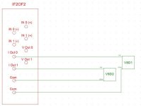
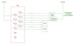
My main question is, can we connect the common from the VFD control board (pin A1, B1, or C1) to our 24VDC common? I've attached a couple connection diagrams from the VFD manual for reference.

If we can, we would be able to power the start (C3) and enable (C5) directly from our relay output card (1769-OW16) using our 24V supply without the need of interposing relays.

We will also be controlling Speed Setpoint (A4) which I have no idea how we would do without connecting commons. We are using a 1769-IF4OF2F (both AI and AO) card to control and monitor speed.

Any help would be greatly appreciated.

Parker VFD IO Connections 2.jpg
 

Attachments

  • Parker VFD IO Connections.pdf
    104.6 KB · Views: 28
Looks like the drive can supply 24V dc 200 ma. is that not enough for your needs? If it is you can keep the control voltages separate.
 
Yes you can do that. We do it all the time, except when we place the drives in a network.
 
Thanks for the responses!

The relay output card we're using doesn't have a V+/V- per channel. It has one V+/8 channels, so we can't connect the VFD's +24V to the card without basically assigning 8 channels to the VFD (we only need 2 channels, start and enable) and I don't want to buy extra equipment if I don't have to.

My other question would be - would I be correct in assuming the A1, B1, and C1 pins are connected internally? Unless there is some reason they might isolate the digital section of the control board from the analog section. I've tried reaching out to the manufacturer but they are unresponsive.

Thanks!
 
usually they are the same but if you are not sure and if you don't have the drive to measure them, just connect all of them together to the panel 0V.

Of course you can connect one output of the plc to the drive input. When you close one of the output relays of the plc, you will be connecting your drive input to the panel 24Vdc and the drive will start. the other plc outputs are free for other things.
 
try this number

Thanks for the responses!

The relay output card we're using doesn't have a V+/V- per channel. It has one V+/8 channels, so we can't connect the VFD's +24V to the card without basically assigning 8 channels to the VFD (we only need 2 channels, start and enable) and I don't want to buy extra equipment if I don't have to.

My other question would be - would I be correct in assuming the A1, B1, and C1 pins are connected internally? Unless there is some reason they might isolate the digital section of the control board from the analog section. I've tried reaching out to the manufacturer but they are unresponsive.

Thanks!
Yes they are tied together.
Ph: (704) 588-3246 Ask for Larry in Tech support.

Also If you don't have it download the DSE lite software and Buy a
Parker SSD Drives # CM351909 Programming Cable
Net Price Each ……… $ 85.00 each
Delivery: Stock at the factory, subject to prior sale
 

Similar Topics

Hi, I would like to assemble a simulator/practice booster pump system that uses PID to maintain steady water pressure under various outlet demands...
Replies
0
Views
86
Hello, I'm trying to delve a little into rs-485 communications for a couple projects of mine. Until now I've been using a delta vfd and a delta...
Replies
2
Views
125
I have an issue with Power Flex 525 during running processing, the VFD stopped suddenly while the PLC and VFD connection ok, VFD does not have any...
Replies
1
Views
131
Hello, I've been trying to learn this a while now and still have not found out how this works. I have an Omron CJ2M PLC and an ABB ACS 355 VFD...
Replies
1
Views
253
Hello, I’m new to this forum and if I’m posting incorrectly let me know. I’ve been having an issue I can’t seem to figure out. I’m sure it’s...
Replies
1
Views
126
Back
Top Bottom