PLC5 PID after processor upgrade

alan_505

Lifetime Supporting Member
Join Date
Feb 2007
Location
Melbourne,Victoria,Australia
Posts
1,045
Has anyone had an issue with a PID control after the processor has been upgraded form a L40E to a L80E.
It does not seem to be controlling properly anymore but only one of the PID's is not behaving.
 
One possibility, and please don't take offense, is that in-memory changes to the misbehaving setup/tuning in the 5/40 were not saved to the offline file before the download to the 5/80.
 
One more thing: if the PID is in a STI routine, check the interval to make sure it was migrated correctly. If not in an STI, check the timer preset for that PID to make sure it is also as it was in the 5/40. Though, if all the loops use the same STI/TON, one would expect all to be affected to some extent (if using I and/or D action).

We have experienced unexplained timer changes with Control Logix up-migrations, though none I know of with PLC-5.
 
When we had to replace the L40E the program that was in it was converted to L80E and then downloaded into new processor. (The processor was crashing and wiping out the program and IP address intermittently (but keeping the DH+ address, so we were able to download locally with DH+ or serial) and but also when we tried to go online after it had been running for a couple of hours after we had reloaded the program, we were advised by RW tech support to change the processor but we only had a L80E to replace it with).

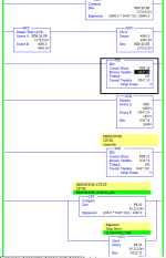
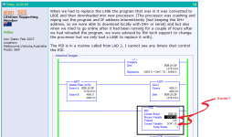
The PID is in a routine called from LAD 2, I cannot see any timers that control the PID.

Capture.PNG
 
Last edited:
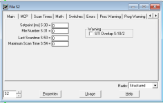
With the unconditional PID scan, I suspect (hope) that LAD 2 is configured as the Selectable Timed Interrupt (STI) routine. You can check this on the processor status (file S2) dialog, and shift over to the STI tab. The interval is the first item listed, and the ladder file number is the second, which should be 2 in your case.

If so, the PID update interval (in seconds) should equal the STI interval (in milliseconds).

Hopefully these S2 values would not change with the upgrade, but you never know if something about the dying processor affected them.

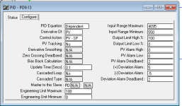
(Edit: that PID Update Time is in the PID Setup dialog on the Configure tab)
 
Last edited:
LAD 2 is the first routine in the program which calls all other routines.
There is nothing entered in the STI tab. S:30, S31, S52, and S:54 all have zero's in them.

Also attached are the screen shots of the PID properties. And they match the backup copies of the program.

Capture3.PNG Capture1.PNG Capture2.PNG
 
Last edited:
I did a similar upgrade a few years ago and ran across some incorrectly programmed PID blocks like yours.

The machinery could cause big problems if the PIDs didn't behave really closely to the way the PLC-5 behaved.

I wanted to make them right and figure out a way to recalculate the gains but the consequences of a failure were too great so my quick and dirty solution was to set the new logic up in a periodic task with an interval set to the average scan time of the old PLC5 it replaced and leave the PID blocks update time alone and all the gains as they were.

It worked out okay and we only made minor tweaks to the gains.
 
See exert from manual.. (third paragraph , execute the PID instruction)

The PID instruction (in a PLC5) should have a timer upstream of the instruction if not in a STI routine.

It should match the time interval of the setting within the PID setup. In your case .1 seconds ( sounds pretty fast to me though)

I would guess your issues are due to different scan times between the two PLC's.
 
Thanks Mickey, that makes sense that the 2 processors could have a different scan time. I will have to work out how to trigger the PID's using a STI or a timer.
PD9:29 generates the PV for PD9:13 which is controlling the speed of the process.
I still cannot work out where the PV for PD9:29 is coming form because it is only in 2 rungs in the program asp per my first post with a picture.
 
In OP's Post #4 of this thread, the Process Variable and the Control Variable are both declared as N347:10 i.e. the same word (see image below).

That does not sound right. Unless the PID does a block transfer starting from that address? But then why would it list the same address? The example in the manual shows different words for those values.

Is the image from Post #4 from the old L40E or the new L80E?

Something is not right.

And you still have to deal with the timing issue.
Untitled.png
 
As a short-term fix, if you think the 5/80 is twice as fast as the 5/40, you can cut the PID Update Time in half to get approximately back to where you were. I do not have a good feel for the scan time difference having never benchmarked a before/after with these processors. Maybe the internet can give some advice.

Longer-term, it is advisable to put in a timer for more predictable performance of these loops, at least with respect to the controller behavior.
 
Yes, drbitboy, that is unusual. There must be some MOVs involved for this to work normally, or at all.
 
Mickey is exactly right: the PLC-5 PID instruction needs to be executed at the same interval as is programmed into its Loop Update Time parameter. This is described in the Instruction Set Reference (1785-RM001 pages 14-10, 14-16, 14-26. etc) and the Help file and in every PID lecture, article, quickstart, and example. The ladder logic examples begin on page 14-30 of that manual.

I have seen plenty of systems like this that essentially work by coincidence: the programmers managed to tune the loops even though the Update time (configured in the PID instruction data block) and the execution time (dependent on the scantime because they are executing the PID unconditionally) are different. Those programs work OK until there's an upgrade or expansion and the execution rate of the routine changes.

This especially bites programmers who had experience with the TI-505 system, which treated PID like a set of configurable loop controllers.

Because this is in LAD2, the default RLL routine for A-B controllers since the 1980s, it is surely not configured to be executed by a Selectable Timed Interrupt (STI).

Another PLC-5 specific thing is that this PID instruction is using the "PD" datatype, which was introduced with the PLC-5 Enhanced controllers. The older PLC-5/15 and /25 Classic controllers used an Integer data file to store the parameters and data for the instruction, and you can retain that method in an Enhanced controller if you wish. PD-based instructions will execute every scan when programmed un-conditionally like this, while an N-file based instruction needs to see a rung condition false->true transition and would never have worked. This is noted in the 1785-RM001 manual on page 14-12.

The best way to resolve this problem is to run the application on a PLC-5/40, even for a short period of time, and capture the Scantime of the LAD2 routine. Then use that to set up Timers or an STI to run this PID code at the same interval.

It still probably won't be actually correct, but it should get the loops working similar to how they worked in the PLC-5/40.
 
Last edited:

Similar Topics

I was wondering if anyone had experience with a PLC5/20 and the PID instruction faulting the processor while changing values in the setup screen...
Replies
3
Views
3,836
I am working on a PLC5 that is doing temp control. However the temp control is working more like ON/OFF and not Proportional control. I am not...
Replies
32
Views
8,643
Has anyone ever converted a the PID instruction from a PLC5 to a CLX platform? The issue I am facing concerns the difference between a PID...
Replies
10
Views
3,472
I'm working on a project to convert an old PLC5 processor to an L63. Below is sample logic of one of the several PID controls from the...
Replies
9
Views
5,041
Hey fellas, I'm in the midst of doing my first translation from 5 to 5000 that also includes PID instructions. I'm just looking for any helpful...
Replies
10
Views
5,514
Back
Top Bottom