Please give some suggestons and programming tips for the problem given below

Mudassir,

I do not understand why you need the >=1 comparison after the 3rd switch NC OHLLS. It seems like you could wire it directly to the NOT AND function block.

Whether or not it is correct depends on the definition of the 3 switches (when they are open and when they are closed). Each switch could be physically set up to be either normally open or normally closed. Your logic must be based on the actual switches.
 
Last edited:
ok.Take a look on these programs they are made on LOGO and some of them are according to my requirement but i need all of you guys suggestion.
I1=UGLLS
I2=OHHLS
I3=OHLLS
 
Last edited:
Give me also a suggestion about this program i dont think so that it looks right check out.
I1=UGLLS
I2=OHLLS
I3=OHHLS
 
Last edited:
This is how it should be. If the lower tank is not low and the upper tank is low run the pump and latch it until the upper tank is full. In real life you would also add an alarm condition for dual limit switches in the upper tank to warn you of a stuck switch.
 
I dont think that it looks right, so check [it] out.
Mudassir,

I agree, that one is not right. You are using one of your sensor switches (OHHLS) to seal in (latch) your pump. Instead, you should use a pump contact Q1 (---||---) to latch the pump on until the OHHLS stops it.

A tank level switch can be open when water is low, or it can be closed when water is low. It depends on the switch brand, model, and design.

You have not first defined the conditions when each physical switch is open or is closed. Until you do that, you are just going in circles. There can be no right or wrong solution, until we know when the switches open and when they close.
 
Last edited:
sorry,Lancie u r right,i should have explained guys with 'open'and 'close' situation as well.
Condition for UGLLS:
1.It is 'open' when Underground tank is filled with water and at that situation the motor remains 'on' automatically.
2.It is 'close' when underground tank is empty at that situation and the motor is 'off' automatically.
Conditions for OHLLS and OHHLS:
1.Both switches are at close intially and the motor is on automatically.
2.When both switches are at 'open' ,the motor is 'off' automatically.
3.The motor is on,even when OHLLS is open and OHHLS is close(NOTE:This is the water filling status).
4.In the consumption state,the motor is off even when OHHLS is close and the OHLLS is open.
5.In the consumption state,the motor is on when both the switches are closed.
This is the whole situation Lancie do u understand it now
 
Last edited:
Thank u Martini Rossy can u tell me software u have used to solve this case.And can i get its demo or full version from any website or URL
 
Thank u Martini Rossy can u tell me software u have used to solve this case.And can i get its demo or full version from any website or URL

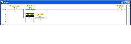
That looks like RSLogix 500, which is used to program Allen-Bradley SLC 500 PLCs.

Contact your local Allen-Bradley rep for pricing...
 
This is the whole situation. Lancie, do [you] understand it now ?
Yes, I understand it now. I understood what you were trying to do after your first post. What I have been trying to explain is this: No one could solve the problem until the switch positions were defined, as each switch could have two possibilites: Closed at High Level, or Closed at Low Level. This is always a problem with real level switches, because many times they have both Normally Open and Normally Closed contacts. The question is which one to use? The PLC logic must be written to use the actual switch wiring.

Now, using your final switch definitions, the logic is simple, like the attached picture. EDIT: Viks suggested that the OHLLS should be closed when low, but the other two switches must be defined also.This shows that it does make a differenece how your switches are physically wired.

PS:
1.Both switches are at close intially and the motor is on automatically.
2.When both switches are at 'open' ,the motor is 'off' automatically.
You still actually did not define your Overhead Tank switches correctly. You defined them in terms of the motor. I call that a backwards definition. They should be defined in terms of the OH Tank Water Level, not the motor. The motor ON/OFf is the RESULT of the switch positions, not the CAUSE. But I read between the lines and defined these as: Both switches closed "initially" means that OHHLS is closed when tank is NOT HIGH, and OHLLS is closed when tank is LOW.

HOUSE WATER TANKS.jpg
 
Last edited:
Hi Guys! Once again i do have a project as u know i belong to a country which does lack in electricity i need to design a system which is related to main electirc supply at home and to the generator .
 
the project i need to design a program in LAD logic or FBD logic is that when the elctricity at my home is gone the generator should start after adelay of 20 seconds and when the elctricity comes back the generator should be off after 20 seconds.as u can from the defined problem it looks as if program dealing On-delay and Off-delay programming.Please program the logic in LogoSoft or any other program in which u find easier in programming but please make it clear to me as well.I wlill thankful to u guys for providing me suggestions
 

Similar Topics

please help me . I have to make this ladder diagram and I can’t figure it out :(
Replies
12
Views
342
Hi , Where i can find Mitsubishi PLC Card end of line & replacement model details. i am looking for Q02CPU replacement model. Please advice. thanks
Replies
2
Views
126
Hello, I am trying to get a Yokogawa Hart pressure Transmitter and a Rosemount Temp Transmitter to read on a 1769-IF4 module on an L33ERM...
Replies
10
Views
378
Please help me, I have solve many week but still not solve it. I found trouble of factory talk studio when I set tag by browse address of OPC...
Replies
0
Views
120
Back
Top Bottom